
In this training from the series of trainings of GeeTech Group, we have collected the training for integrating Siemens PLC with RC Pro HMI for beginners.
Simplifying Device Communication in Automation Projects, Learn how to seamlessly connect RS PRO HMI to S7-1200 or S7-1500 PLC via Ethernet!
Join us as we swiftly configure and program a PLC in TIA Portal, develop and set up an HMI application in piStudio, and validate the connectivity between these systems – all within the next 10 minutes!
This insightful piece is presented in collaboration with RS, a leading omnichannel provider of industrial product and service solutions. Discover how they streamline your processes efficiently!
Let’s kick off the process by initiating the PLC configuration in TIA Portal.
Siemens PLC Configuration
Within TIA Portal, I initiated a new project and incorporated an S7-1211 PLC for the exercise. Utilizing the S7-1211 PLC was a choice based on the availability in my lab; however, feel free to utilize S7-1200 or S7-1500 PLC models if you’re following this guide at home.
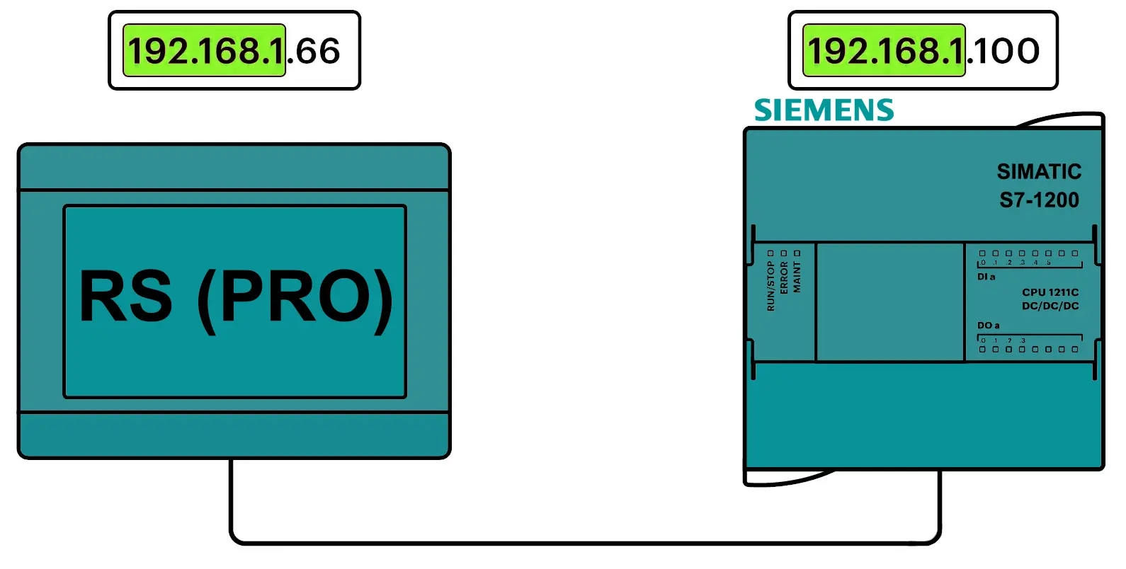
Within the Devices & Networks Editor, I accessed the PLC’s property configuration by selecting the PLC itself. To ensure seamless communication between the PLC and HMI through an Ethernet network, I configured an IP address for the PLC within the same subnet as the HMI.
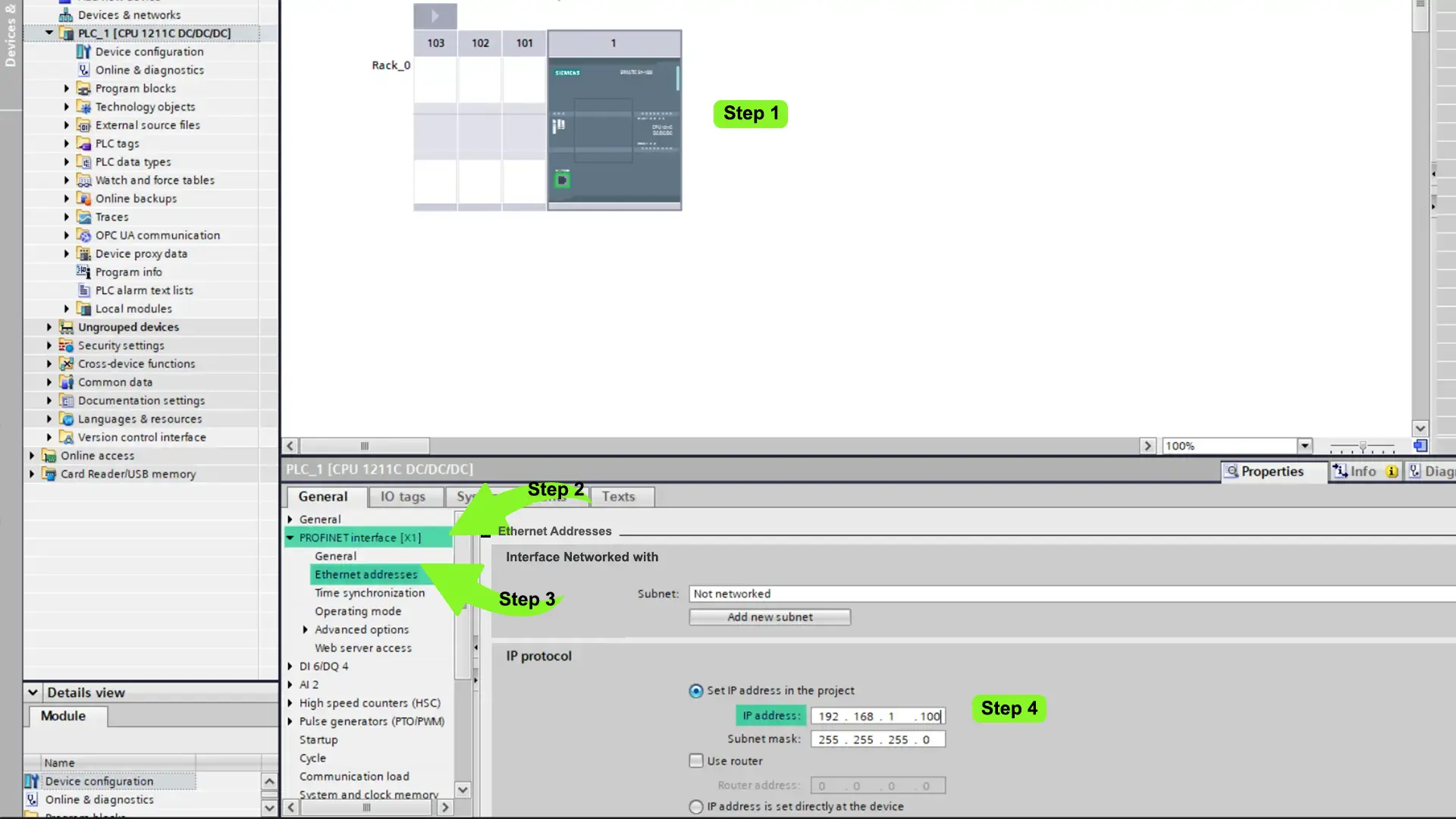
To set up the PLC’s IP address, I navigate to the PROFINET interface [X1] > Ethernet addresses section and allocate the IP address 192.168.1.100 to the PLC.
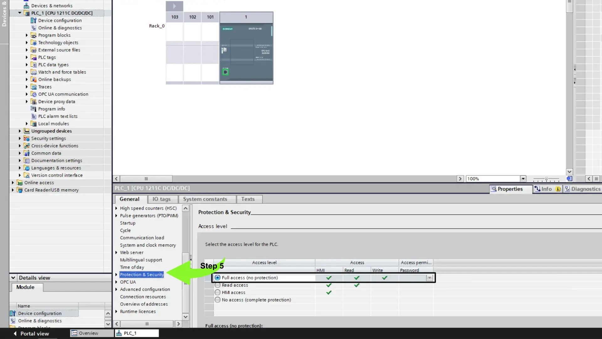
In addition to setting up the PLC’s IP address, I need to enable external device access to the PLC’s data and activate the communication protocol facilitating data exchange between the PLC and HMI.
To achieve this, I navigate to the Protection and Security section within the PLC’s properties.
Within this section, I adjust the access level to Full Access, granting external devices permission to read and write all the data within the PLC.
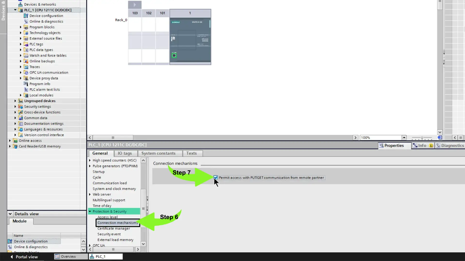
Finally, I must activate PUT/GET communication in the PLC. This protocol is essential for exchanging data between the PLC and the RS PRO HMI.
To enable PUT/GET communication, I navigate to the Connection mechanisms page and toggle on the option to Permit access with PUT/GET communication from the remote partner.
After configuring the PLC, we can create basic logic for testing HMI communication in the future.
PLC Programming:
To initiate programming, I double-click on the Main OB to access the object.
I then proceed to create a simple seal-in circuit comprising one permissive and two interlock conditions.
After programming, the next step involves defining tags for the project. In this demonstration of how an RS PRO HMI interacts with various tag types in an S7 PLC, we will utilize Memory, Global Output, and Global Input tags.
For instance, the process control can be initiated or halted via the HMI using the hmiStart and hmiStop tags, situated at addresses M0.0 and M0.1, respectively.
Additionally, a physical stop button is installed to cease the process. This stop button is linked to the PLC’s I0.0 input, for which I create a corresponding tag, btnStop.
Moreover, during operation, the PLC activates the physical output Q0.0, signifying the process is running, and this action is linked to the tag bcnRunning.
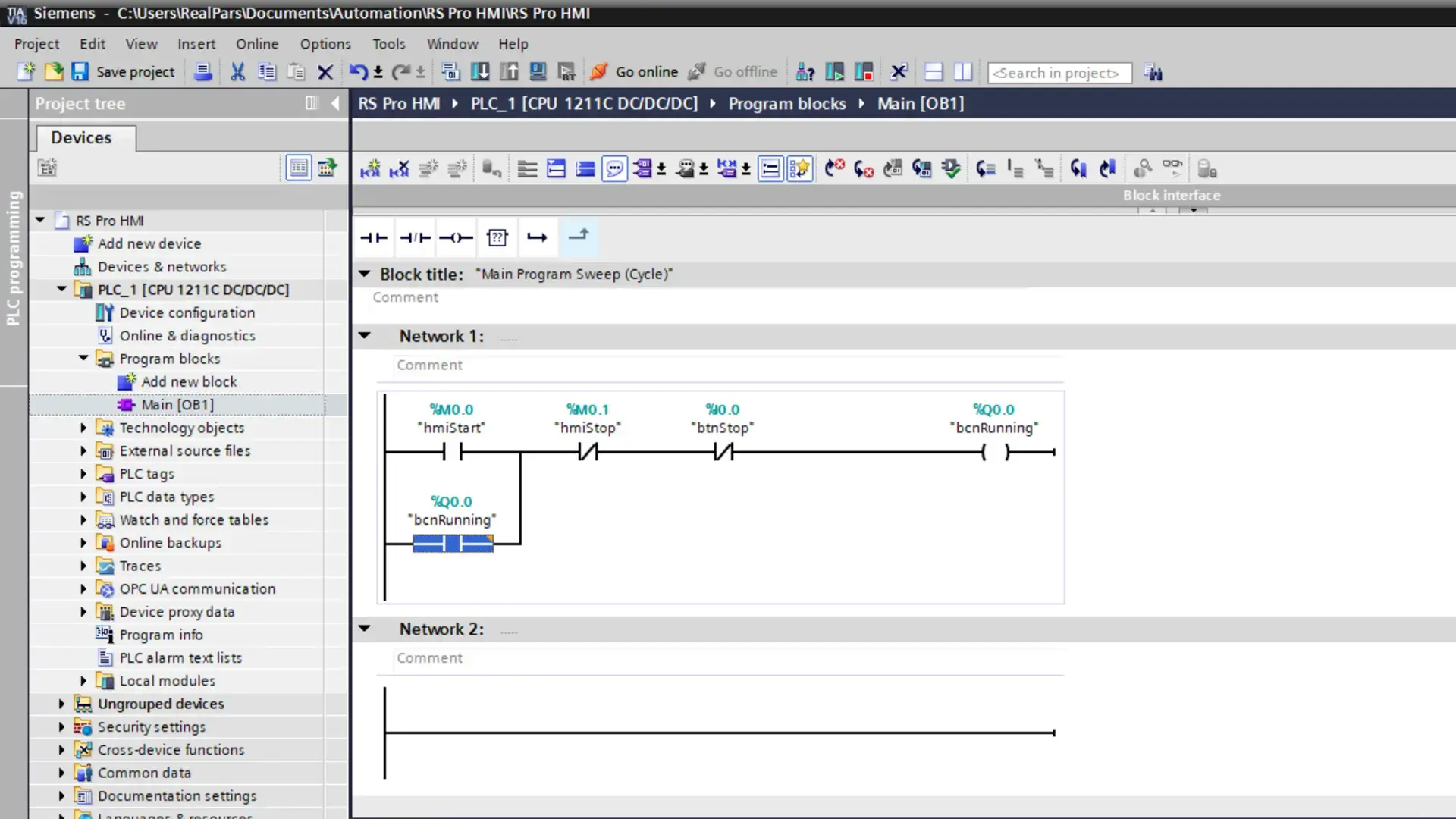
After finalizing the logic configuration, I proceed to compile my project and then download it to the PLC.
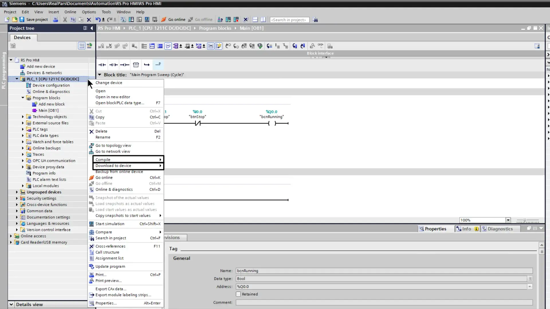
With the PLC programming completed, now we shift our focus to piStudio, the development platform for RS PRO HMIs.
Setting up the HMI:
I initiate a new project within piStudio.
In the project creation dialog, I input the project name, select the specific RS PRO HMI model, and configure the communication parameters. For this instance, I opt for an Ethernet connection to interface with a Siemens S7-1200 PLC.
Upon finalizing these configurations, I press ‘Finish’ to generate the project.
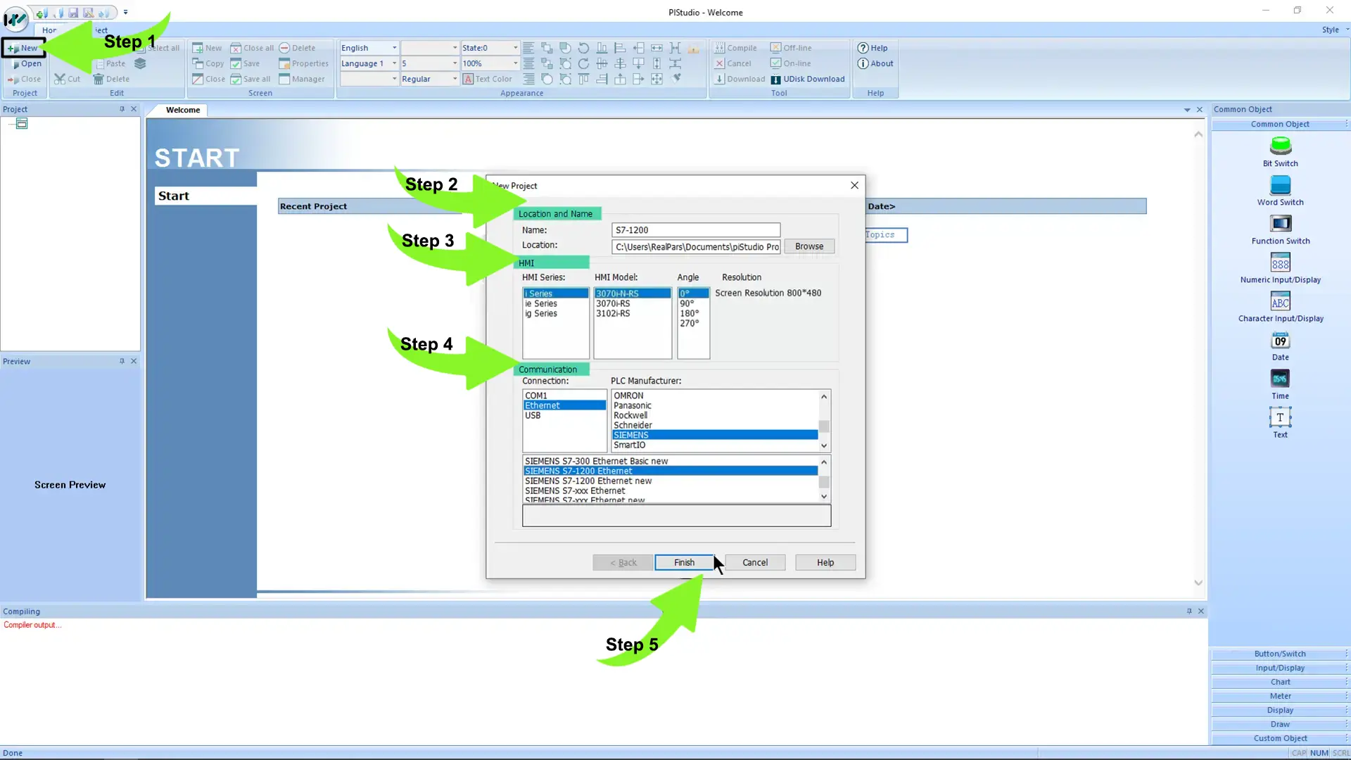
In the project, it is crucial to define the PLC’s IP address for HMI communication. This setup is performed within the project’s communication configuration settings.
To access the communication configuration, navigate to the Project tab on the toolbar and select Communication.
In the Communication dialog box, click on ‘Settings’ next to the Device IP field to input the IP address of the PLC that the HMI will interact with. Note that adjustments are solely made to the IP address, while other settings remain unchanged.
Upon completing the configuration, confirm the modifications by clicking OK on both dialog boxes to save the configuration changes and exit the dialogs.
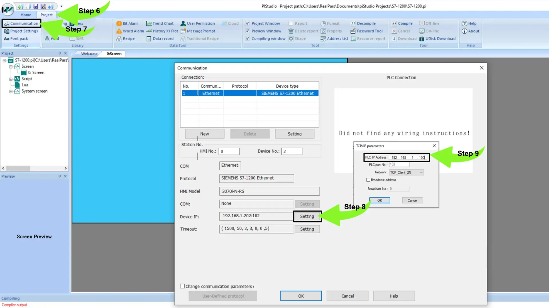
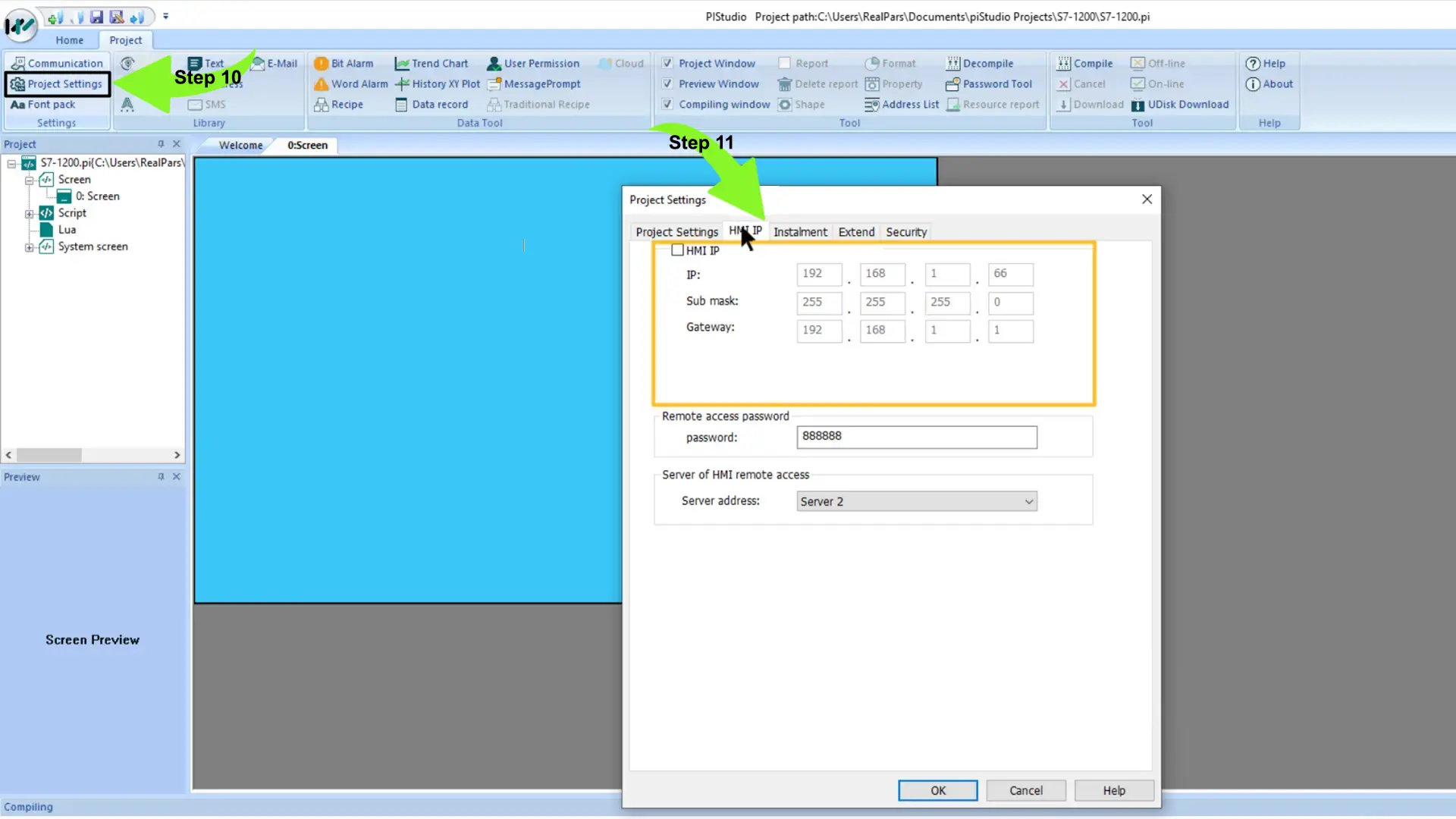
Additionally, it is necessary to designate the IP address of the HMI.
To accomplish this, access the Project Settings and input the IP address of the HMI in the HMI IP tab.\
With the HMI now configured, we are ready to create our HMI application.
Steps to create the HMI application:
1. Build the HMI application.
2. Add objects to the HMI screen by dragging them from the toolbox and dropping them on the canvas.
To start, let’s add a Bit Switch to the canvas according to the instructions below:
– Place the Bit Switch object on the canvas.
– Double-click on the object to access its configuration menu.
– Configure the Bit Switch to write to a specific tag in the PLC by clicking on the Edit button next to the Write Address field.
– In the dialog box that appears, set the PLC tag’s address as M0.0, which corresponds to the hmiStart tag’s address.
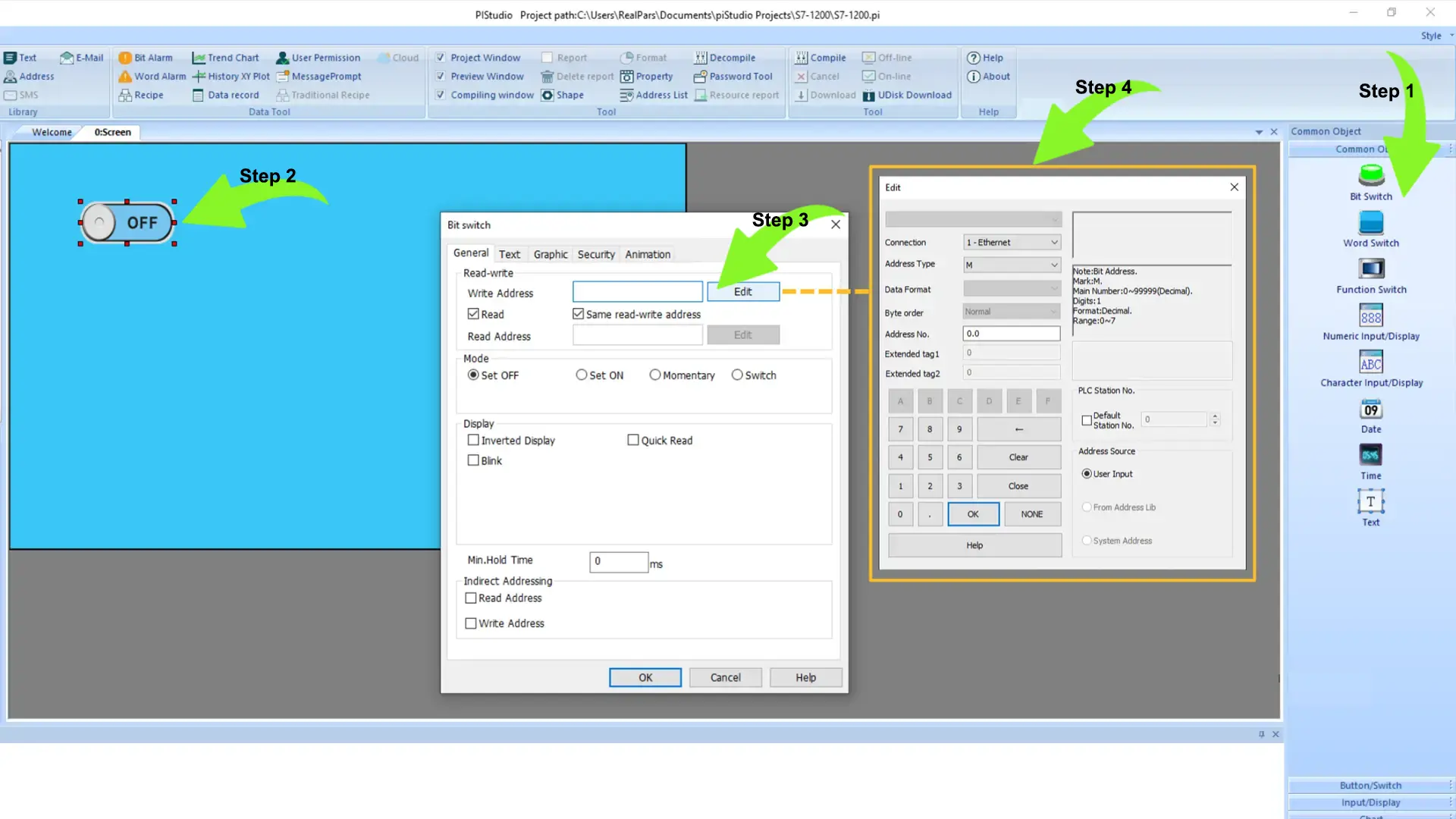
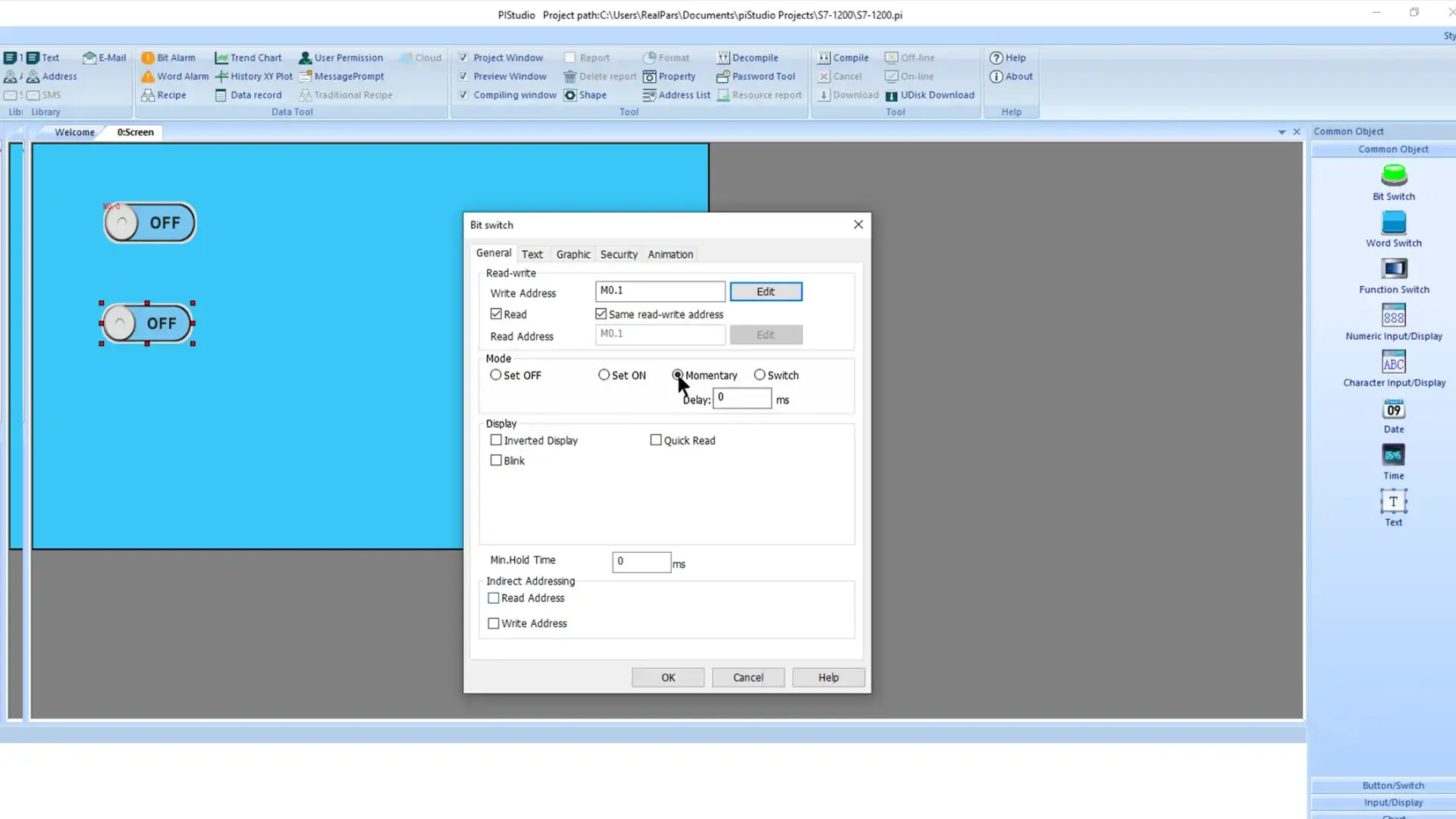
I clicked OK twice to save the configuration, then repeated the process to add a second Bit Switch object for the hmiStop tag using the address M0.1.
Additionally, I specified the mode of this Bit Switch. I selected Momentary. In Momentary mode, a Bit Switch writes the value True to its associated tag while the switch is active.
In addition to manipulating tag values through HMI writes, we can also display tag statuses by reading their values.
I added a Bit Lamp object from the toolbox to visually represent the state of a Boolean tag in the SIEMENS PLC.
By double-clicking on the object, I could access its configuration dialog and specify the tag address for reading. In this case, I am reading from the address I0.0, which corresponds to the physical stop button.
I follow the same procedure to include another Bit Lamp that reads from the address Q0.0, corresponding to the output that activates during operation. Incorporating text labels Our HMI is nearly complete at this point. To provide clarity on the functions of the objects in our HMI, I will add some text labels. To achieve this, I select the Common Object folder in the toolbox and place a Text object above the hmiStart Bit Switch on the canvas. I then double-click on the object to access its configuration dialog and modify the text to say HMI Start.
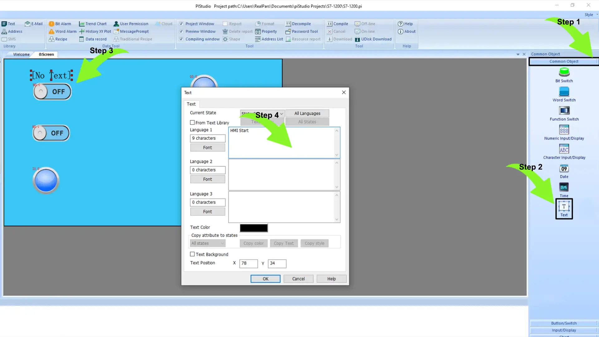
I duplicate this text object by copying and pasting to provide labels for the remaining objects on the canvas. If preferred, I can utilize the alignment and positioning tools located on the toolbar to arrange and align the objects accurately on the canvas, just like demonstrated here.
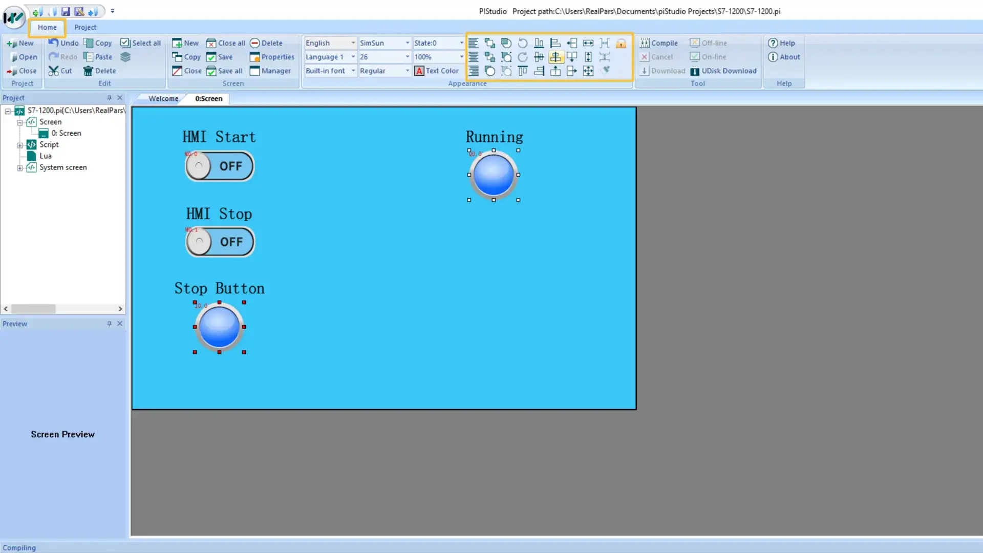
Now that the Human-Machine Interface (HMI) development is complete, we can compile the HMI by clicking the Compile button on the toolbar and then proceed to download the application to the HMI device.
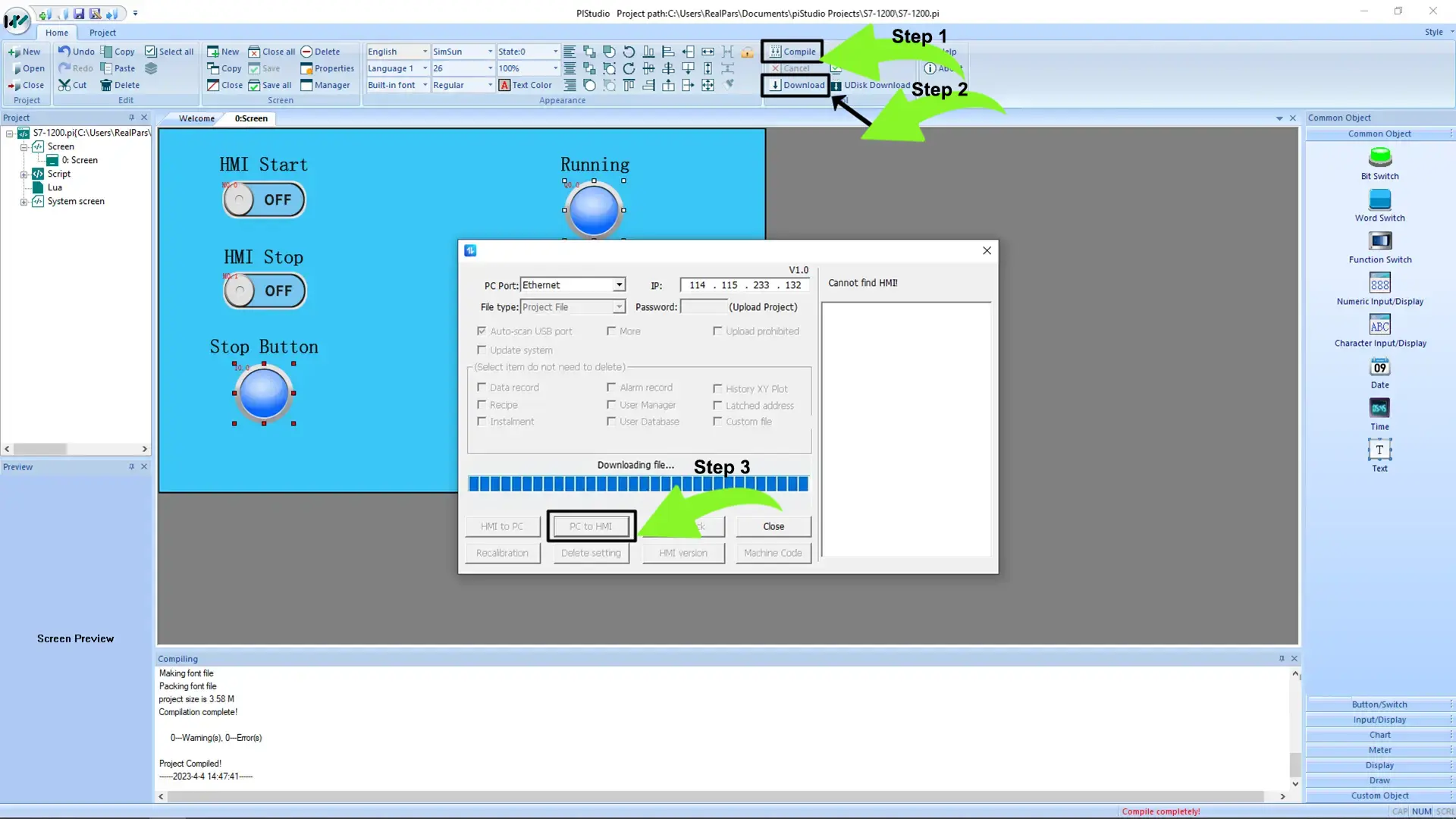
After downloading the application, we can proceed to test the communication to ensure that everything functions as intended.
To test the communication:
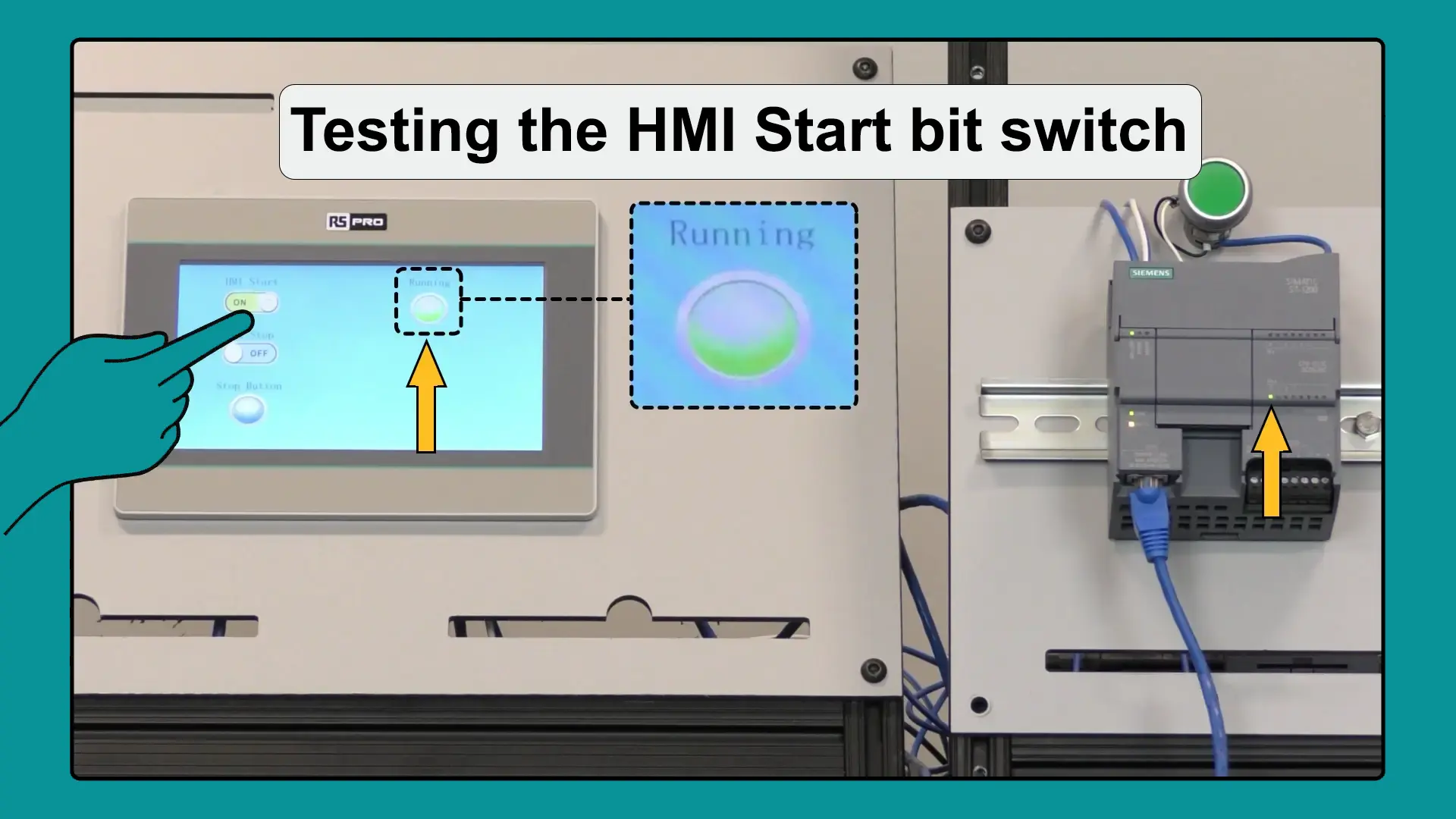
1. Activate the HMI Start bit switch on the HMI interface.
2. When the switch is turned on, it will write the value ‘True’ to the hmiStart tag in the Siemens PLC, and the output bcnRunning will switch to ‘True’.
I will verify the operation by checking that the tag bcnRunning displays ‘True’ through the updated appearance of the Running Bit Lamp.
Lastly, I can switch the state of the physical input I0.0 on the Siemens PLC. By doing so, I observe the value of the physical input altering the Stop Button Bit Lamp on the HMI interface.
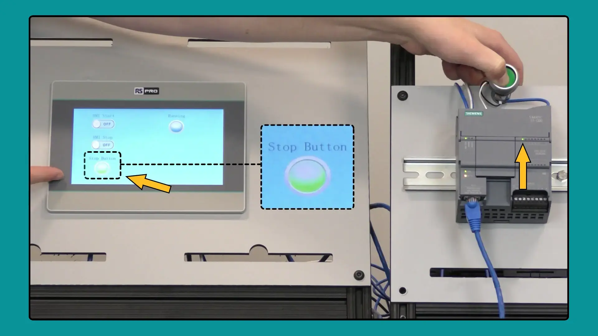
At this juncture, we can affirm that the communication between the PLC and HMI is functioning smoothly.
Conclusion
I introduced the seamless process of establishing communication between a Siemens S7-1200 PLC and an RS PRO HMI using TIA Portal and piStudio.
In detail, we covered setting an IP address for the PLC, configuring the PLC’s access level, and enabling PUT/GET communication.
After finalizing the PLC setup, we delved into configuring the IP address for HMI-PLC communication and mapping HMI objects to PLC tags.


