Are you curious about the working principle of MCCBs (Molded Case Circuit Breakers) and how they protect electrical systems? In this article, we will explore in detail how MCCBs function, their key types, and why they are essential for electrical safety and reliability. Whether you’re an electrical engineer or just interested in electrical components, this guide will help you understand the fundamental operation and applications of MCCBs, including popular models like Schneider MCCB and Siemens MCCB.
What is MCCB (Molded Case Circuit Breaker)?
Molded Case Circuit Breakers (MCCBs) are vital devices used in modern electrical distribution systems to protect circuits from overloads and short circuits. Acting as a safeguard, MCCBs interrupt fault currents to prevent damage to electrical equipment and ensure safety.
Unlike other types of circuit breakers that use mediums such as oil, SF6 gas, or vacuum to extinguish the electrical arc, MCCBs rely on air as the dielectric medium to safely break the circuit. While air has a lower dielectric strength compared to other mediums, it remains an efficient, safe, and cost-effective choice for low-voltage applications.
Thanks to their reliability and adaptability, MCCBs are widely employed in residential, commercial, and industrial settings. In this article, we will explore the working principle, different types, construction details, and key applications of MCCBs to provide a comprehensive understanding of these essential electrical components.
Understanding the Primary Function of MCCB in Circuit Protection
The primary function of a Molded Case Circuit Breaker (MCCB) is to provide reliable protection against overloads and short circuits by automatically disconnecting the circuit when the current exceeds a predefined threshold. When a load is connected, the current flow between the source and the load increases due to the thermal effect. If this current exceeds the set limit, the MCCB’s overcurrent protection mechanism is activated, causing an open circuit to prevent potential damage to the system.
MCCBs are specifically designed to handle both low and high fault currents, making them a critical component in any electrical installation, from small residential systems to large industrial plants. In addition to overload protection, MCCBs also offer short circuit protection, which instantly breaks the circuit when a fault current is detected.
One of the major advantages of MCCBs is their durability. They are engineered to withstand over a million operation cycles, ensuring long-term reliability and efficiency in service. This makes them a cost-effective solution for long-term circuit protection.
Key Functions of MCCBs:
Molded Case Circuit Breakers (MCCBs) perform several essential functions to protect electrical circuits and ensure safety:
1. Overload Protection
Overloading occurs when the current exceeds a preset limit for a certain period, potentially damaging equipment and causing fire hazards. MCCBs detect this condition using a bimetallic strip that trips the breaker to disconnect the circuit automatically.
2. Short Circuit Protection
A short circuit happens when live wires touch each other or a neutral wire, causing a sudden surge of very high current. MCCBs can interrupt short circuit currents up to 200,000 amps within milliseconds (around 0.04 seconds), minimizing damage to electrical systems.
3. Manual Switching
MCCBs also allow manual switching to turn ON or OFF the power supply to connected circuits, which is useful during maintenance or emergency shutdowns.
4. Adjustable Trip Settings
Many MCCBs come with adjustable trip settings, enabling customization of protection thresholds based on the needs of the specific electrical installation.
By combining these features, MCCBs provide reliable protection and operational control, making them vital components in residential, commercial, and industrial electrical systems.
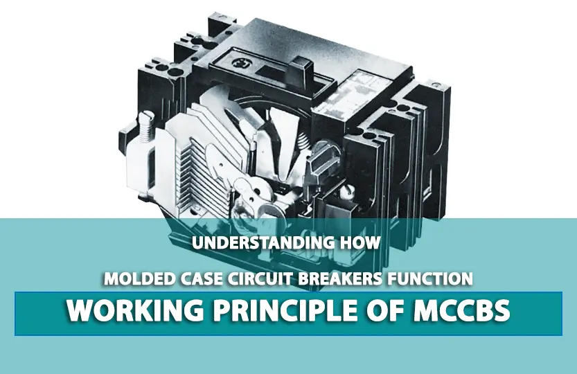
Molded Case Circuit Breaker Working Principle
What is the Working Principle of MCCB?
At its core, the working principle of an MCCB is straightforward. When an overcurrent or short circuit occurs in an electrical circuit, the MCCB detects the fault and automatically interrupts the flow of current. This action helps to prevent damage to the circuit and the connected electrical devices, as well as ensuring the safety of the personnel operating the system. In industrial applications, models such as Schneider MCCB and Siemens MCCB are widely trusted for their reliability and performance.

The image above shows a detailed view of a Molded Case Circuit Breaker (MCCB) with its key components labeled. Understanding these components is crucial for comprehending how MCCBs function to provide reliable circuit protection.
1. Molded Frame:
The external structure that houses all internal components. This frame is typically made of strong, durable materials to provide physical protection and insulation. The molded frame ensures that the MCCB can withstand environmental stress and operational wear, enhancing its long-term reliability.
2. Operating Mechanism:
This component is responsible for manually or automatically opening and closing the circuit. It allows for the control of electrical flow, enabling users to interrupt the circuit when needed or when an overload or short circuit is detected.
3. Arc Extinguisher (Internal Component):
When a fault occurs, an arc forms as the circuit is interrupted. The arc extinguisher safely dissipates the arc energy, preventing damage to the breaker and surrounding equipment. This is a critical safety feature in MCCBs.
4. Contacts (Internal Component):
These are the points of connection between the input and output terminals of the breaker. When the breaker is closed, the contacts allow electrical current to flow through. In the event of a fault, these contacts open to break the circuit and stop the flow of current.
5. Trip Unit:
The trip unit is the brain of the MCCB. It monitors the current flowing through the breaker and triggers the mechanism to open the contacts when the current exceeds a set limit, protecting against overloads and short circuits.
Each of these components works together to ensure the MCCB can provide reliable protection against electrical faults, safeguarding both the equipment and the users.
Types of MCCBs
Molded Case Circuit Breakers (MCCBs) come in different types based on their tripping characteristics, similar to Miniature Circuit Breakers (MCBs). These types are classified according to their tripping curves, which determine how quickly the breaker responds to overcurrent conditions.

Type B MCCB
Type B MCCBs trip when the current reaches 3 to 5 times their rated current, with a tripping time ranging from 0.04 to 13 seconds. They are the second most sensitive type after Type Z, designed to react to small surges. Because of their high sensitivity, they should not be used in environments with normal low surges, as they may trip frequently. Typical applications include resistive loads and other resistive elements.
Type C MCCB
Type C MCCBs trip at current surges 5 to 10 times their rated current, with tripping times between 0.04 to 5 seconds. These breakers tolerate higher surges compared to Type B and are commonly used for small inductive loads such as small motors, transformers, and electromagnets, especially in industrial settings.
Type D MCCB
Type D MCCBs are designed to trip at 10 to 20 times their rated current, with very fast tripping times of 0.04 to 3 seconds. They can withstand the highest surges among MCCB types, making them ideal for highly inductive loads with large inrush currents, like large industrial motors.
Type K MCCB
Type K MCCBs trip at 10 to 12 times their rated current, with tripping times ranging from 0.04 to 5 seconds. These breakers are suitable for inductive loads with high inrush currents, such as certain types of motors.
Type Z MCCB
Type Z MCCBs are the most sensitive type, tripping at just 2 to 3 times their rated current. They are specifically designed for sensitive semiconductor-based equipment, including medical devices and other expensive electronics vulnerable to even minor current surges.
Choosing the right type of MCCB based on the load characteristics and surge tolerance is critical to ensure optimal protection and minimize nuisance tripping in electrical systems.
MCCB Working Principle With Diagram
Construction and Working Principle of MCCB (Molded Case Circuit Breaker)
Understanding the internal construction of an MCCB is key to grasping how it protects electrical circuits. MCCBs are composed of several critical parts, each playing a vital role in the breaker’s operation:

Key Components of MCCB:
Molded Case (Cover and Base)
The durable protective shell that houses all internal components.
Arc Extinguishing Device (Arc Chute)
A set of insulated metal plates that safely split and extinguish the electric arc generated when the circuit is interrupted.
Switching Mechanism
Enables manual ON/OFF operation of the breaker via the handle.
Handle
Used to manually open or close the breaker; also indicates the current state (ON, OFF, or TRIPPED).
Trip Button
A red button to manually trip the breaker for testing purposes.
Relay Unit (Thermal and Magnetic Trip Units)
Detects overloads and short circuits and triggers the breaker to trip.
Adjustable Knob
Found in electronic MCCBs, this allows setting the tripping current threshold.
Contacts
Conductive parts that open and close the electrical circuit.
Terminals
Connect the MCCB to external electrical circuits.
The MCCB operates through a combination of thermal and magnetic detection mechanisms:
- – Thermal Mechanism: A bimetallic strip bends under excessive current, causing the breaker to trip.
- – Magnetic Mechanism: A solenoid generates a magnetic field during high-current events, pulling a plunger to trip the breaker instantly.
Overall, this detailed diagram effectively explains the internal workings and components of an MCCB, crucial for understanding its role in circuit protection.
The MCCB (Molded Case Circuit Breaker) automatically disconnects the circuit during overload or short-circuit conditions using a combination of thermal and magnetic mechanisms, while the arc extinguishing unit ensures system safety and protection.
Understanding the Mechanism of MCCBs
MCCBs consist of three main components: a trip unit, a current-carrying mechanism, and an arc quenching system. The trip unit is responsible for monitoring the current passing through the circuit breaker and triggering the opening of the contacts in case of an abnormal current flow. The current-carrying mechanism ensures the safe interruption of the current, while the arc quenching system extinguishes any arc that may form during the interruption process.
How do you calculate MCCB settings
To set the overload protection on an MCCB (Molded Case Circuit Breaker):
1. Determine the Rated Current (In): Identify the rated current of the MCCB, for example, 1000A.
2. Adjust the Long Pickup (Ir): Set the long pickup value to match the full load current. If the full load current is 800A, adjust the setting to 0.8 (representing 80% of the MCCB’s rated current).
3. Calculate Ir: Multiply the long pickup value by the MCCB’s rated current.
– Example: Ir = 0.8 x 1000A = 800A
This adjustment ensures the MCCB will trip if the current exceeds 800A continuously, providing effective overload protection.
Setting Short Circuit and Ground Fault Protection
1.Short Circuit Protection:
Set the magnetic trip (short circuit protection) value according to the expected fault current levels in your system. This is typically a multiple of the rated current (In).
2. Ground Fault Protection:
Adjust the ground fault settings to detect and interrupt leakage currents to prevent damage and hazards. This setting is usually lower than the short circuit protection setting.
Verifying and Testing
- Always verify the settings against your system’s requirements and safety standards.
- Conduct tests to ensure the MCCB functions correctly under simulated fault conditions.
- Refer to the manufacturer’s manual for precise instructions tailored to your specific MCCB model.
How Does the Trip Unit Work?
The trip unit in an MCCB is equipped with sensors that continuously monitor the current flow in the circuit. When the current exceeds a pre-set threshold, the trip unit sends a signal to the operating mechanism, causing the contacts to open and disrupt the current flow. This fast and precise action helps to protect the circuit from damage and averts potential hazards.
Benefits of Using MCCBs
MCCBs offer several advantages over traditional fuses and other circuit protection devices. They provide better protection against overloads and short circuits, are more reliable and durable, and offer adjustable trip settings for customized protection. Additionally, MCCBs are easier to install and maintain, making them a preferred choice for modern electrical systems. To explore high-quality options, check out Schneider MCCB and Siemens MCCB solutions available in the market.
Here is a more detailed breakdown of MCCB benefits:
1.Protection & Safety
Overload Protection: MCCBs prevent circuits from overheating and damaging wires and equipment by detecting and interrupting prolonged excessive current flow.
Short Circuit Protection: They quickly detect sudden, high-current surges from short circuits and trip the circuit, minimizing damage and fire risks.
Advanced Safety Features: MCCBs incorporate features like arc dissipation and integral earth leakage protection to further safeguard against electrical hazards.
2.Performance & Reliability
Adjustable Trip Settings: The ability to fine-tune tripping current levels allows for precise protection tailored to specific applications and current characteristics, such as motor starting inrushes.
High Breaking Capacity: MCCBs are designed to withstand and clear significant fault currents, ensuring reliable performance even under demanding conditions.
Durability and Long Lifespan: Encased in a protective molded housing, MCCBs are more resilient to environmental factors and offer a longer mechanical and electrical life than fuses, reducing replacement frequency.
3.Design & Versatility
Compact Size: Their compact design makes them suitable for use in smaller electrical panels and crowded installations, saving valuable space.
Wide Range of Applications: MCCBs are versatile and used in various settings, from industrial and commercial buildings to heavy-duty equipment like welding machines and large motors.
Ease of Reset: Unlike fuses, MCCBs can be easily reset after tripping, providing continuous operation after a fault.
Conclusion
In conclusion, understanding the working principle of MCCBs is vital for ensuring the safety and efficiency of electrical systems. By incorporating MCCBs into your electrical distribution system, you can protect your circuits from overloads and short circuits, minimize downtime, and safeguard your equipment and personnel. So, the next time you encounter an electrical fault, remember the essential role that MCCBs play in maintaining a secure and reliable electrical environment.
mccb working principle pdf
To download the article working principle of MCCB in PDF format, click on the following link:
Frequently Asked Questions
What Is the Difference Between an RCD and RCBO?
✅ An RCD (Residual Current Device) provides protection against earth faults by detecting leakage currents and disconnecting the circuit. An RCBO (Residual Current Breaker with Overcurrent) combines the functions of an RCD and an MCB (Miniature Circuit Breaker), protecting against both earth faults and overcurrent (overloads and short circuits).
Why is MCCB better than MCB?
✅An MCCB (Molded Case Circuit Breaker) is better than an MCB (Miniature Circuit Breaker) because it offers higher current ratings, adjustable trip settings, and protection against a wider range of electrical faults, including overload, short circuit, and ground faults. MCCBs are suitable for industrial and commercial applications requiring higher power capacities and more robust protection, whereas MCBs are typically used for lower-power residential and light commercial applications.
How to set MCCB settings?
✅1. Identify the Rating:
- Check the rated current (In) of the MCCB to ensure it matches your system requirements.
✅2. Adjust the Trip Settings:
- Thermal Trip Adjustment: Set the overload protection by adjusting the thermal trip dial to the desired value (usually a percentage of the rated current).
- Magnetic Trip Adjustment: Set the short circuit protection by adjusting the magnetic trip dial to the appropriate level, based on the expected fault current.
✅3. Verify the Settings:
- Double-check that the settings align with your system's electrical parameters and safety requirements.
✅4. Test the MCCB:
- Conduct a test to ensure the MCCB operates correctly under simulated fault conditions.
✅5. Consult the Manual:
- Refer to the manufacturer's manual for specific instructions and recommended settings for your MCCB model.
How do you calculate MCCB settings?
✅ To set the overload protection on an MCCB (Molded Case Circuit Breaker):
1. Determine the Rated Current (In): Identify the rated current of the MCCB, for example, 1000A.
2. Adjust the Long Pickup (Ir): Set the long pickup value to match the full load current. If the full load current is 800A, adjust the setting to 0.8 (representing 80% of the MCCB’s rated current).
3. Calculate Ir: Multiply the long pickup value by the MCCB’s rated current.
- Example: Ir = 0.8 x 1000A = 800A
Contact GeeTech Group :