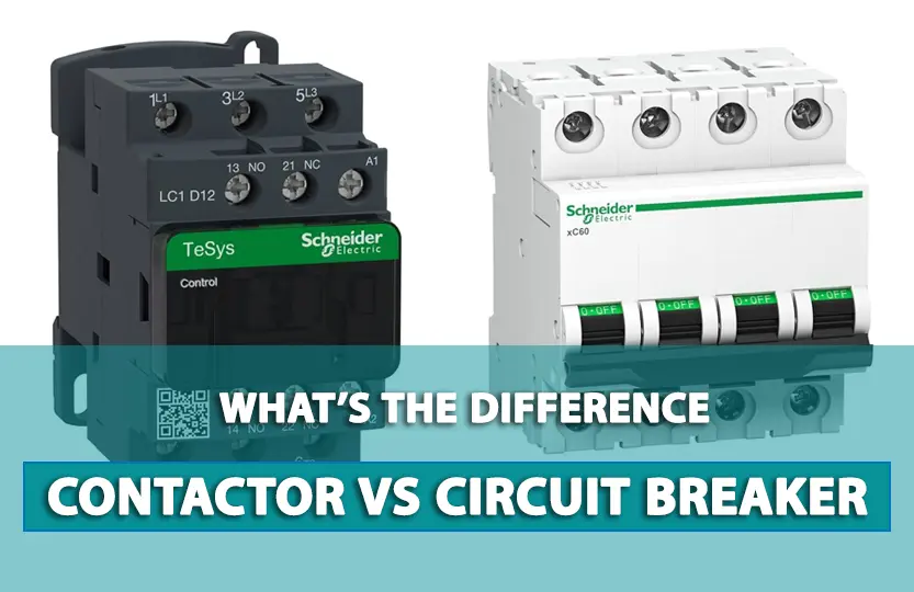
If you’re looking to understand the difference between a circuit breaker and a contactor, you’ve come to the right place. These two electrical components may seem similar, but they serve very different purposes. In this article, we’ll explain their definitions, working principles, and key differences to help you decide when to use each one.
In this article, we’ll break down their definitions, working principles, key differences, and even compare two popular brands: Siemens Sirius and Schneider Electric.
Definition and Basic Information of Circuit Breaker and Contactor
Circuit breaker
A circuit breaker is a crucial electrical safety device designed to automatically interrupt the flow of electric current when it detects abnormal conditions such as overloads, short circuits, or ground faults. Its primary role is protection, ensuring that wiring, appliances, or machinery are shielded from damage caused by excessive current.
Unlike traditional switches that require manual operation, circuit breakers are engineered to sense electrical faults in real-time and respond instantly. They contain electromechanical mechanisms combined with thermal or magnetic trip units that detect fault conditions.
There are several types of circuit breakers used depending on the application and voltage level, including:
Miniature Circuit Breaker (MCB) for residential protection
Molded Case Circuit Breaker (MCCB) for commercial and industrial use
Air Circuit Breaker (ACB) and Vacuum Circuit Breaker (VCB) for high-voltage scenarios
Their internal design typically includes movable and fixed contacts, arc extinguishing chambers, and a spring mechanism that allows for quick disconnection. Because of these protective features, circuit breakers are often mandatory in all electrical installations, from homes to heavy industrial systems.
What is a Contactor?
A contactor is an electrically controlled switch used for repeated switching of an electrical circuit, especially when a high current needs to be controlled by a low-power signal. Unlike circuit breakers, contactors are not designed to interrupt short circuits or faults. Instead, they are used for switching electrical loads on and off, such as motors, lighting, heating systems, and capacitors.
The working principle of a contactor revolves around an electromagnetic coil. When voltage is applied to this coil, it generates a magnetic field that pulls in a set of contacts to close the circuit and allow current to flow. When the control signal is removed, a spring mechanism separates the contacts, breaking the circuit.
Contactors are designed for:
Remote control of machines and systems
Frequent operation and rapid switching
Use in automation systems, HVAC, and motor control centers (MCCs)
They come in various sizes and ratings, with some capable of handling currents over 1000A. Some advanced contactors also include auxiliary contacts for signaling, overload relays for protection, and noise suppression modules.
In essence, while a circuit breaker protects, a contactor controls — and both play essential roles in modern electrical systems.
Read More :
What is a Contactor? Introduction and applications of Contactors
Working principle of Circuit Breaker and Contactor
Working Principle of Circuit Breakers – Explained with Diagram

How Does a Circuit Breaker Work?
Let’s explore the simplified working principle:
Normal Condition: Current flows smoothly through the breaker as long as the connected load is within the safe range.
Overload: If the current exceeds safe levels over time, the heat bends a bimetallic strip, triggering a trip.
Short Circuit: A sudden surge causes a strong magnetic field in the coil, instantly breaking the circuit.
Disconnection: Internal contacts are pulled apart, stopping the flow and preventing damage.
Internal Structure and Operation of an MCB
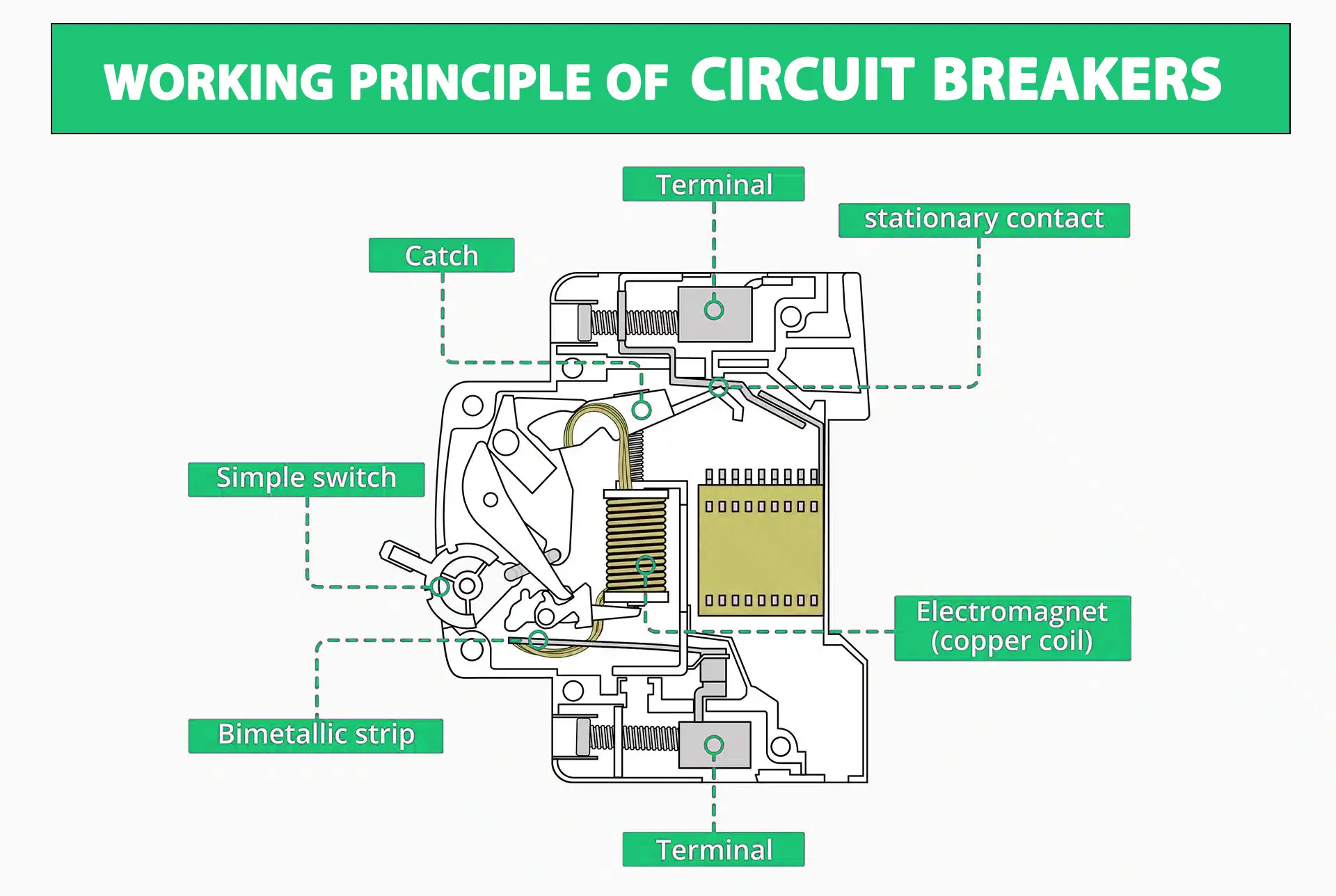
Now, let’s take a closer look at the internal components and operation of a typical Miniature Circuit Breaker (MCB), as shown in the diagram above:
1. Terminal
There are two terminals (top and bottom). They serve as input and output points for the current. Electricity enters from one terminal, passes through internal components, and exits from the other.
2.Electromagnet (Copper Coil)
This coil detects short circuits. When a sudden surge of current occurs, the magnetic field generated by the coil pulls a mechanical trigger, quickly separating the internal contacts to stop the current flow.
3. Bimetallic Strip
Designed for overload protection, this strip consists of two metals that expand at different rates. As the current increases over time, the strip bends due to heat, mechanically opening the circuit to prevent damage.
4. Simple Switch
This is the manual lever that allows users to turn the breaker on or off. It’s directly connected to the internal spring and catch mechanism.
5. Catch
The catch holds the internal contacts in place. When the breaker trips (thermally or magnetically), the catch is released, and the contacts separate to interrupt the circuit.
6. Stationary Contact & Moving Mechanism
The stationary contact stays fixed, while the moving part is linked to a spring-loaded mechanism. When tripped, the spring pulls the moving contact away, creating a gap to stop the current. Arcing that occurs during this process is typically managed in an arc chute (not shown in the diagram).
Summary of How It Works:
1.Normal load: Current flows through the coil and bimetallic strip.
2.Overload: Heat bends the strip, opening the circuit slowly.
3.Short circuit: The Magnetic field trips the mechanism instantly.
4.Trip action: The catch releases, the contacts separate, and the current stops.
This mechanism ensures that connected devices are protected from both gradual overload and sudden short circuits, making circuit breakers essential in any electrical installation — residential, commercial, or industrial.
Working Principle of Contactors (Explained with Diagram)

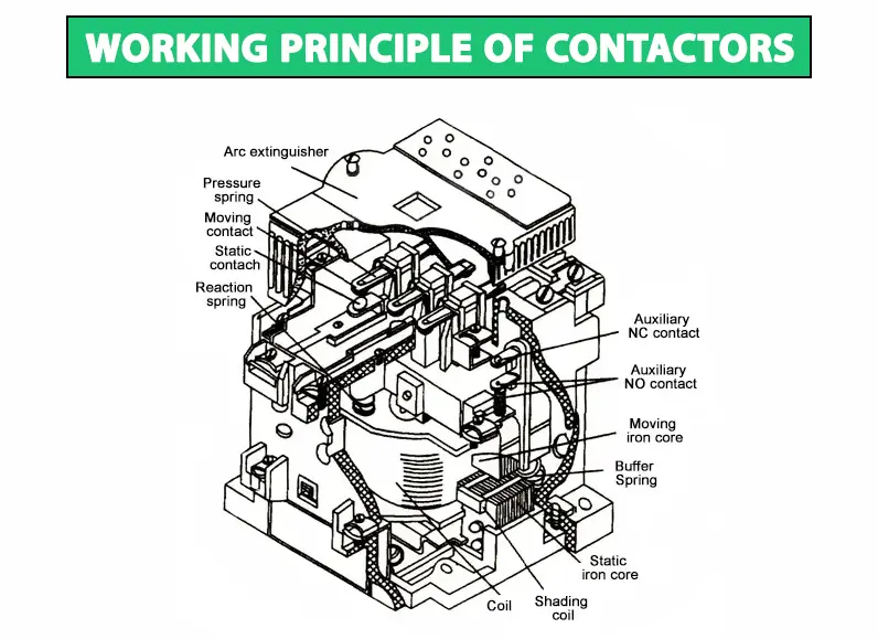
The image above showcases the internal structure and operational mechanism of a typical contactor. Let’s break down each labeled component and understand how it contributes to the contactor’s performance.
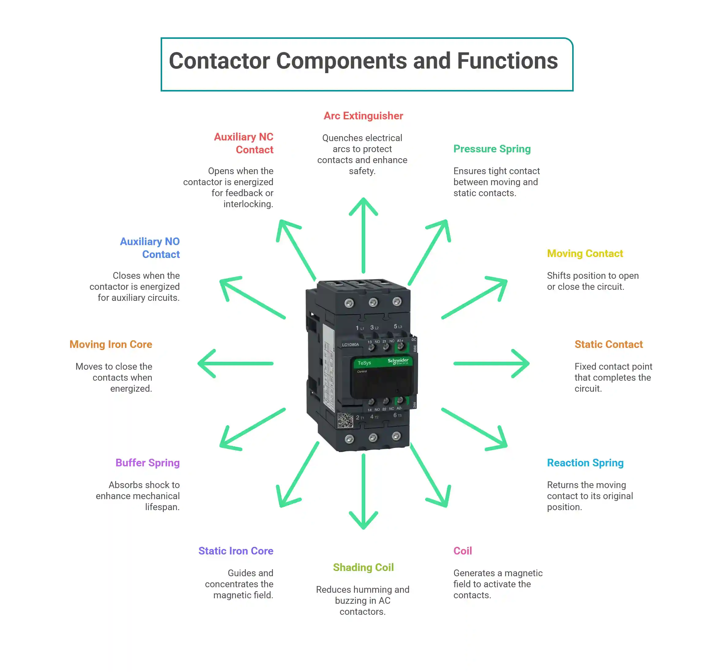
Key Components and Their Functions:
1.Arc Extinguisher:
When the contacts open under load, electrical arcing may occur. The arc extinguisher quenches this arc quickly, protecting the contacts and enhancing safety.
2.Pressure Spring:
This spring ensures the moving contact is pressed tightly against the static contact when the contactor is energized, ensuring solid electrical connection.
3.Moving Contact:
This is the contact that shifts position when the coil is energized. It connects with or separates from the static contact to open or close the circuit.
4.Static Contact:
The fixed contact point that pairs with the moving contact. When both are in contact, the circuit is complete, allowing current to flow.
5.Reaction Spring:
Works against the electromagnetic force. Once the coil is de-energized, this spring helps return the moving contact to its original (open) position.
6.Coil:
The core component of the electromagnetic system. When power is supplied, it generates a magnetic field that pulls the moving iron core and activates the contacts.
7.Shading Coil:
Found in AC contactors, this small copper ring reduces humming and buzzing by delaying the magnetic flux in part of the core. It ensures smooth operation.
8.Static Iron Core:
The fixed part of the magnetic circuit. It helps guide and concentrate the magnetic field created by the coil.
9.Buffer Spring:
Absorbs shock and prevents excessive impact when the moving iron core is attracted to the static core. This enhances the lifespan of mechanical parts.
10.Moving Iron Core:
Drawn toward the static iron core when the coil is energized. Its motion causes the contacts to close.
11.Auxiliary NO Contact (Normally Open):
These auxiliary terminals are used for control purposes. When the contactor is energized, NO contacts close, allowing auxiliary circuits to operate.
12.Auxiliary NC Contact (Normally Closed):
These contacts are closed when the contactor is off and open when the contactor is energized, used for feedback or interlocking logic.

How It Works (Step-by-Step):
1.When voltage is applied to the coil, it produces an electromagnetic field.
2.This magnetic force pulls the moving iron core toward the static iron core, moving the moving contacts into connection with the static contacts.
3.Pressure springs help ensure strong contact.
4.Power now flows through the circuit—e.g., to start a motor.
5.Once the coil is de-energized, the reaction spring pushes the contacts back to their original open position, interrupting the current.
6.Any arc formed during disconnection is safely extinguished by the arc extinguisher.
7.The shading coil prevents vibrations or noise, especially with an AC supply.
Electrical Contactor
The main role of a contactor in an electrical system is to connect the load to the current at high voltage levels efficiently. Contactors offer several advantages, including rapid opening and closing capabilities. A moving contactor becomes essential for precise control or when transitioning between high and low voltage requirements.
Circuit Breaker
Conversely, a circuit breaker operates automatically by interrupting the current supply in the event of a short circuit or overload. Professionals can manually interact with a circuit breaker by connecting it to electrical contacts. Therefore, during regular operation, this mechanism functions similarly to a switch.
Other Important Differences Between Circuit Breaker and Contactor:
electronic contactor serves as a straightforward switching device, while a circuit breaker functions as a protective system. The main role of a contactor is power control, whereas a circuit breaker focuses on protection.
Under normal conditions, a contactor operates, whereas a circuit breaker only acts in response to faults. Contactors typically handle medium voltage levels, contrasting with circuit breakers that handle high voltage scenarios.
Using a contactor may result in more sparking and flashing, whereas circuit breakers eliminate this risk. Contactors do not support automation, whereas circuit breakers can automatically start and stop when faults arise.
In a contactor, electromagnetism enables the connection between movable and fixed contacts, while circuit breakers require both mechanical and electromagnetic pressure for the connection. Contactors lack ARC quenching mechanisms, whereas high-voltage circuit breakers have this safety feature.
Notably, contactors lack an electric voltage sensing system, unlike circuit breakers that incorporate current and voltage sensing components. For further details, feel free to reach out to GeeTech.
Main Differences Between Circuit Breaker and Contactor
| Feature | Circuit Breaker | Contactor |
|---|---|---|
| Primary Function | Protection | Control |
| Interrupt Faults? | Yes | No |
| Manual Operation | Yes | Usually No |
| Arc Quenching | Yes (especially in high voltage) | Limited |
| Voltage Handling | High Voltage | Medium Voltage |
| Automation Capability | Limited | Designed for automation |
Key Differences Between Siemens Sirius Contactors and Schneider Electric Contactors
Siemens Sirius Contactor: Reliable Power Control Solutions
Siemens Sirius Contactor: Known for their reliable medium voltage applications, Siemens Sirius contactors are designed for efficient power control. [Explore Siemens Sirius Contactors] to find more about their features and applications, ensuring you select the right contactor for your needs.
Schneider Electric Contactor: Advanced Industrial Applications
Schneider Electric Contactor: Schneider offers a variety of contactors suitable for different industrial scenarios, emphasizing safety and performance. [Check Schneider Electric Contactors]to understand how they can improve your systems with advanced technology.


