Schneider Power Factor Controller
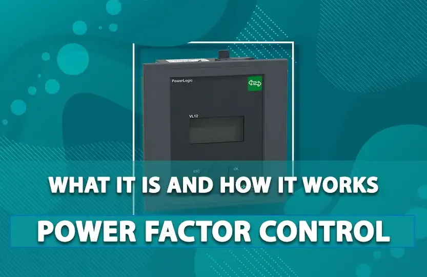
Schneider Electric is renowned for its innovative solutions in energy management and automation. Among its extensive range of products, the Schneider Power Factor Controller stands out for its efficiency and reliability in optimizing power usage and improving power quality. This controller is designed to enhance the performance of electrical systems by maintaining an optimal power factor, which in turn reduces energy consumption and costs.
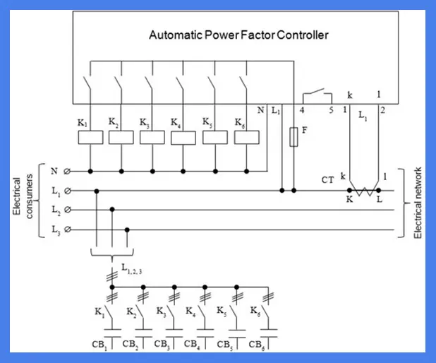
Schneider Power Factor Controller Diagram

Power Factor Controller
A power factor controller is an essential device in electrical systems, used to manage and correct the power factor. The power factor measures the efficiency with which electrical power is converted into useful work output. A power factor closer to 1 indicates efficient utilization of electrical power, while a lower power factor signifies poor power usage. By using a power factor controller, industries can avoid penalties from utility companies, reduce energy losses, and improve the overall efficiency of their electrical systems.
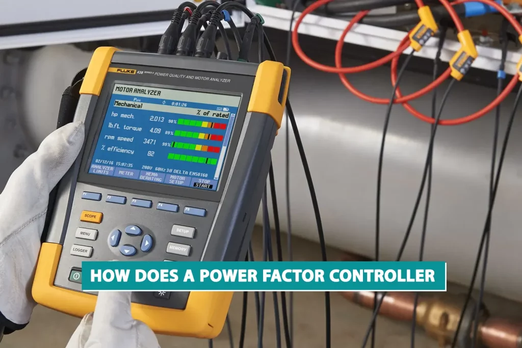
How Does a Power Factor Controller Work?

Power factor controllers operate by continuously monitoring the voltage and current of a load. They calculate the power factor using advanced mathematical algorithms to determine the TRUE RMS values, considering the harmonic content in the current and voltage. When the power factor deviates from the desired value, the controller activates or deactivates capacitor banks to correct the power factor. This dynamic adjustment helps maintain a power factor close to unity, ensuring efficient energy usage and minimizing losses.
A power factor controller (PFC) is a device designed to improve the power factor of an electrical system, which is essential for efficient energy consumption and cost savings. Here’s how it works:
Continuous Monitoring and Calculation
Power factor controllers continuously measure the voltage and current of the load. They use mathematical algorithms to calculate the TRUE RMS (Root Mean Square) values of these measurements. The TRUE RMS values are essential because they take into account the harmonic content of both current and voltage, leading to more accurate power factor readings. Harmonics are voltage or current waveforms at multiples of the fundamental frequency, and they can distort the power factor measurement if not properly accounted for.
Optional Serial Interface Input
In some configurations, the power factor can also be obtained via the serial interface of a power electronic recorder (REP) user output. This method does not involve harmonic calculation, which might be sufficient for specific applications but can lead to less accurate measurements compared to the method that considers harmonics.
Capacitor Bank Activation
When the inductive power factor of the system falls below a predetermined setpoint, the controller activates one or more capacitor banks. Capacitor banks are groups of capacitors used to provide reactive power compensation. By doing so, the controller corrects the power factor, bringing it closer to unity (1.0), which is ideal. This process improves the efficiency of the electrical system by reducing the phase difference between voltage and current.
Protective Features
Power factor controllers include several features to protect the capacitor banks and ensure their longevity:
1.Rest Time:
This is a programmed delay that prevents a capacitor bank from being turned on immediately after being turned off. Without this rest time, repeated rapid switching could damage the capacitors and reduce the lifespan of the contactors, which are devices that connect the capacitors to the power grid.
2.Switch-Off Point:
When the power factor exceeds the programmed switch-off point, indicating that the system’s inductive loads have decreased, the controller deactivates one or more capacitor banks. This process continues until the power factor returns to within the desired range.
3.Overvoltage Protection:
The controller disconnects the capacitor banks when the grid voltage reaches excessively high values. This feature prevents prolonged overvoltages, which can damage the capacitors and other components of the electrical system.
4.Harmonic Protection:
If the harmonic content of the current and voltage becomes too high, the controller disconnects the capacitor banks to avoid resonances within the installation. Resonances can cause significant damage to the capacitors and other system components.
What is a Digital Power Factor Controller?
A digital power factor controller represents the latest advancement in power factor correction technology. Unlike traditional analog controllers, digital power factor controllers offer enhanced precision, programmability, and user-friendly interfaces. They come equipped with features such as real-time monitoring, data logging, remote communication capabilities, and advanced diagnostics. These controllers can adapt to varying load conditions more effectively, providing more accurate and reliable power factor correction.
Important notes on power factor controller installation
1.Positioning of Current Transformer (CT):
Place the CT immediately after the power source (substation, transformer, or switchboard) to accurately measure current from loads and capacitor cells. Ensure the wiring diameter is at least 2.5 mm².
2.Voltage Measurement Connection:
When measuring voltage between two phases, use phases different from the one monitored by the CT. Connect the TC to the controller’s TC1 and TC2 inputs accordingly. For voltage measurement between phase and neutral, connect the CT to the phase being used and link it to the TC1 and TC2 inputs.
3.Contactor Drive Protection:
Each contactor drive should have its individual fuse to ensure protection.
4.Wiring Separation:
Keep voltage and current measurement wiring (CT) in conduits separate from contactor controls by a minimum of 10 cm. Avoid passing wiring through power cable ducts to prevent interference from capacitor currents.
5.Specific CT Placement:
Install a dedicated CT for current measurement (preferably in a xxx/5A transformation ratio). If a measuring instrument with a CT is already in place, it can be utilized, provided the CT signal remains in series with the controller. Ground the CT terminals if necessary.
6.Supply Voltage and Contactor Connections:
Ensure separation between the common wire of contactors and the controller’s power source. Each drive output should not exceed 250VAC/5A.
7.Optional REP Interface Usage:
When using the optional REP interface without CTs and grid voltage connection, electrical measurements for these parameters will reset to zero.
8.Voltage Application for Measurement:
Apply voltage to the measurement input to display both voltage and current parameters in the electrical measurements menu. Failure to do so will result in resetting these parameters to zero.
Benefits of Using Schneider Power Factor Controllers
Energy Savings:
By maintaining an optimal power factor, Schneider power factor controllers help reduce energy losses and lower electricity bills.
Improved Power Quality:
These controllers mitigate issues related to poor power factor, such as voltage drops and equipment overheating, thereby enhancing the overall power quality.
Extended Equipment Life:
With efficient power factor correction, electrical equipment experiences less strain and operates more efficiently, leading to longer service life.
Compliance with Regulations:
Schneider power factor controllers help industries comply with utility regulations and avoid penalties associated with poor power factor.
Conclusion
Schneider power factor controllers are a vital component in modern electrical systems, offering advanced technology and reliable performance for power factor correction. By understanding their functionality, benefits, and installation requirements, industries can significantly improve their energy efficiency and power quality, resulting in cost savings and enhanced operational reliability. Whether opting for traditional or digital power factor controllers, Schneider Electric provides robust solutions tailored to meet diverse industrial needs.


