


Schneider Electric
Schneider Electric is a multinational corporation specializing in energy management and automation solutions. With operations in over 100 countries, the company offers a wide range of products and services for various industries, including residential, commercial, and industrial.
Schneider Electric is focused on sustainability and innovation, aiming to help their customers manage energy efficiently and reduce their environmental impact.
Schneider Power Factor Controller
Schneider Electric offers a range of power factor controllers designed to improve energy efficiency and reduce electricity costs by optimizing the power factor in electrical systems. These controllers are typically used in industrial and commercial settings where reactive power can lead to increased energy costs and reduced system efficiency.

Key Features of Schneider Power Factor Controllers
Automatic Control: Schneider power factor controllers automatically manage the power factor by switching capacitors on and off based on the real-time requirements of the electrical system.
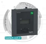
User-Friendly Interface: These controllers often feature intuitive interfaces with LCD displays, making them easy to configure and monitor.
Advanced Measurement Capabilities: They provide precise measurements of various electrical parameters, including voltage, current, power factor, reactive power, and harmonic distortion.
Programmable Settings: Users can program various settings to tailor the controller’s operation to the specific needs of their system, including target power factor levels and switching sequences.
Communication Options: Many Schneider power factor controllers come with communication capabilities, allowing integration with building management systems (BMS) and remote monitoring.
Harmonic Filtering: Some models are equipped with harmonic filtering features to reduce harmonic distortion in the electrical system, improving overall power quality.
Alarm and Protection Functions: These controllers include alarm and protection functions to safeguard the system against faults such as overvoltage, undervoltage, and overheating.
Common Models and Series
Schneider Electric offers several models of power factor controllers, each with varying features and capabilities to suit different applications. Some common series include:
VarPlus Logic: This series offers advanced power factor correction with features like multi-stage regulation, real-time monitoring, and modular design for easy expansion.
VarSet: A comprehensive power factor correction system that can be customized to meet specific requirements, often used in larger industrial applications.
AccuSine: Although primarily an active harmonic filter, the AccuSine series also provides power factor correction, offering a dual solution for power quality improvement.
For more detailed information on specific models and technical specifications, you can visit GeeTech Group official website or consult their product catalogs.
Power Factor Controller
A power factor controller (PFC) by Schneider Electric is designed to improve the power factor in electrical systems, which enhances energy efficiency and reduces electricity costs. It automatically switches capacitors to correct the power factor, continuously monitors electrical parameters, and provides protection against overvoltage, undervoltage, and harmonics. Schneider PFCs, like the VarPlus Logic and AccuSine series, offer advanced monitoring, dynamic compensation, and modular designs suitable for various applications such as industrial facilities, commercial buildings, and renewable energy systems, ensuring improved system efficiency, compliance with regulations, and enhanced power
VPL12N
The Schneider Electric VarPlus Logic (VPL) VPL12N is an advanced power factor controller designed to optimize the power factor in electrical systems, thereby enhancing energy efficiency and reducing electricity costs.
The VarPlus Logic is a simple and intelligent relay that measures, monitors, and controls reactive energy, maintaining the power factor. It can control up to 12 steps of capacitors for reactive power compensation, ensuring precise power factor correction.

The VPL12N features easy commissioning, step size detection, and monitoring, along with various alarms for enhanced system protection. It comes with a user-friendly interface and real-time monitoring of electrical parameters.
The device provides reliable performance with protections against overvoltage, undervoltage, and harmonics, making it suitable for various industrial and commercial applications. By improving power quality and reducing losses, the VPL12N contributes to the overall efficiency and stability of electrical systems.

Reviews
There are no reviews yet.