METSEPM1120HCL10RS
EASYLOGIC PM1130H DUAL P&E RLY RS CL 0.5
- Stock status:
- Call for availability
- Manufacturer:
- Schneider
- Product code:
- METSEPM1120HCL10RS
Main documents
Related products
| Range | EasyLogic |
|---|---|
| Product name | EasyLogic PM11XXH RS |
| Device short name | PM1120H |
| product or component type | Energy meter |
| Power quality analysis | Total harmonic distortion |
|---|---|
| Device application | Energy monitoring |
| Type of measurement | Current Voltage Frequency Power factor Phase angle RPM Peak demand power Harmonic distorsion (I THD & U THD) Active power Active energy |
| Metering type | Reactive power Q, Q1, Q2, Q3 Rotation speed Voltage U21, U32, U13, V1, V2, V3 Power factor and displacement PF (signed, four quadrant) Unbalance current Frequency Demand power P, Q, S Apparent power S, S1, S2, S3 Phase currents Active power P, P1, P2, P3 Active, reactive, apparent energy (signed, two quadrant) Phase current I1, I2, I3 RMS Average current Iavg Average voltage Vavg Calculated neutral current Unbalance voltage |
| counter functions | ON-load hour counting Power interruption ON hour counting |
| [Us] rated supply voltage | 48…277 V AC 45…65 Hz 48…277 V DC |
| Network frequency | 60 Hz 50 Hz |
| [In] rated current | 1 A 5 A |
| type of network | 2P + N 2P 3P 3P + N 1P + N |
| Maximum power consumption in VA | 4 VA at 240 V between phase and neutral |
| Maximum power consumption in W | 2 W at 240 V |
| Display type | 8 segments LED |
| Display colour | Red |
| Messages display capacity | 3 fields of 4 characters |
| Display digits | 12 digit(s) – 14.2 mm in height |
| communication of data | All counters Instantaneous and demand values Reading of measurements Last cleared log Revolution speed |
| Tamperproof of settings | Protected by access code |
| Sampling rate | 32 samples/cycle |
| Measurement current | 5…6000 mA |
| Signal | Voltage (impedance 5 MOhm)4 x Current 0.005…10 A (impedance 0.3 MOhm)6 x |
| Measurement voltage | 46…277 V AC 50…60 Hz between phase and neutral 80…480 V AC 50…60 Hz between phases 277…999000 V AC 50…60 Hz with external VT |
| Frequency measurement range | 45…65 Hz |
| Measurement accuracy | Current +/- 0.5 % Voltage +/- 0.5 % Frequency +/- 0.05 % Power factor +/- 0.01 Reactive power +/- 2 % Active power +/- 1 % Apparent power +/- 1 % Active energy +/- 1 % Reactive energy +/- 2 % Apparent energy +/- 1 % Harmonic distorsion (I THD & U THD) +/- 5 % |
| Accuracy class | Class 1 active energy conforming to IEC 62053-21 Class 1 reactive energy conforming to IEC 62053-24 |
| Demand intervals | 1 s |
| Local signalling | Green LED: activity Red LED: output signal 1…9999000 pulse/ k_h (kWh, kVAh, kVARh) |
| Communication port protocol | Modbus at 4800 bps, 9600 bps, 19200 bps, 38.4 Kbps even/odd or none – 2 wires, insulation 2500 V |
| Communication port support | Screw connector: RS485 |
| Data recording | Energy consumption logs |
| Material | Polycarbonate |
| Flame retardance | V-0 conforming to UL 94 |
| mounting mode | Flush-mounted |
| Mounting support | Framework |
| Provided equipment | Installation guide |
| installation category | III |
| Type of installation | Indoor installation |
| Measurement category | Category III 480 V |
| Electrical insulation class | Class II |
| Connections – terminals | Current circuit: screw clamp terminals (bottom) 2.08…3.31 mm² cable(s) Voltage circuit: screw clamp terminals (top) 0.82…3.31 mm² cable(s) Control circuit: screw clamp terminals (top) 0.82…3.31 mm² cable(s) Communication: screw clamp terminals (bottom) 0.33…3.31 mm² cable(s) |
| Tightening torque | Current circuit: 0.9…1 N.m Philips No 2 screwdriver Voltage circuit: 0.9…1 N.m Philips No 2 screwdriver Control circuit: 0.9…1 N.m Philips No 2 screwdriver Communication: 0.5…0.6 N.m Philips no 1 screwdriver |
| Wire stripping length | Current circuit: 3.68 mm Voltage circuit: 7 mm Control circuit: 7 mm 7 mm |
| Standards | IEC 61010-1:ed. 3 UL 61010-1:ed. 3 |
| Product certifications | CE conforming to IEC 61010-1 CULus conforming to UL 61010-1 CULus conforming to CSA C22.2 No 61010-1 C-Tick |
| Width | 96 mm |
| Depth | Outside : 13 mm Panel : 49 mm |
| Height | 96 mm |
| net weight | 300 g |
| Electromagnetic compatibility | Electrostatic discharge conforming to IEC 61000-4-2 Radiated radio-frequency electromagnetic field immunity test conforming to IEC 61000-4-3 Electrical fast transient/burst immunity test conforming to IEC 61000-4-4 Surge immunity test conforming to IEC 61000-4-5 Conducted RF disturbances conforming to IEC 61000-4-6 Magnetic field at power frequency conforming to IEC 61000-4-8 Voltage dips and interruptions immunity test conforming to IEC 61000-4-11 Emission tests conforming to FCC part 15 class A Emission tests conforming to FCC part 15 Subpart C Emission tests conforming to FCC part 15 Subpart E |
|---|---|
| Overvoltage category | III |
| IP degree of protection | IP51 front: conforming to IEC 60529 IP30 body: conforming to IEC 60529 |
| Relative humidity | 5…95 % at 50 °C |
| Pollution degree | 2 |
| Ambient air temperature for operation | -10…60 °C |
| ambient air temperature for storage | -20…70 °C |
| Operating altitude | <= 2000 m |
| Service life | 7 year(s) |
| Unit Type of Package 1 | PCE |
|---|---|
| Number of Units in Package 1 | 1 |
| Package 1 Height | 4.88 cm |
| Package 1 Width | 9.6 cm |
| Package 1 Length | 9.6 cm |
| Package 1 Weight | 265 g |
| Unit Type of Package 2 | S03 |
| Number of Units in Package 2 | 18 |
| Package 2 Height | 30 cm |
| Package 2 Width | 30 cm |
| Package 2 Length | 40 cm |
| Package 2 Weight | 4770 g |
| Unit Type of Package 3 | P06 |
| Number of Units in Package 3 | 144 |
| Package 3 Height | 105 cm |
| Package 3 Width | 60 cm |
| Package 3 Length | 80 cm |
| Package 3 Weight | 38.2 kg |
Product Description
METSEPM1120HCL10RS
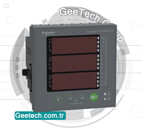
The Schneider Electric EasyLogic PM1120H (product code METSEPM1120HCL10RS) is a versatile and reliable power and energy meter designed for monitoring and managing energy consumption and electrical parameters. Here are the key features and specifications of this device:
Key Features:
1.Measurement Capabilities:
- Power and Energy Monitoring: Monitors active and apparent power or energy consumption, run mode, and current.
- Energy Accuracy: Provides Class 1 active energy accuracy as per IEC 62053-21 standard.
- Parameters Measured: Measures active and reactive energy, ensuring comprehensive energy monitoring.
2.Data Storage:
- Integrated Data Storage: Capable of saving up to 10 years of integrated data, ensuring long-term data availability and analysis.
3.Display:
- LED Display: Features a 3-row, 14 mm height, 7-segment, 4-digit LED display that clearly shows current and power measurements.
4.Communication:
- Protocol: Supports Modbus RTU communication protocol.
- Interface: Equipped with an RS485 port for robust and reliable communication.
5.Mechanical Specifications:
- Width: 96 mm
- Height: 96 mm
- Depth: 90 mm
Summary:
The EasyLogic PM1120H power meter by Schneider Electric is an essential tool for precise energy management and monitoring. With its accurate measurement capabilities, long-term data storage, clear display, and reliable communication options, it is designed to help users effectively monitor and manage their energy consumption and electrical parameters. This meter is particularly valuable for applications that require detailed energy analysis and reporting over extended periods.
Frequently Asked Questions
How does a power monitor work?
✅ A power monitor measures electrical parameters such as voltage and current in real time. It uses sensors like current transformers (CTs) or Rogowski coils to collect data, then calculates power and energy consumption using internal processors. Advanced models, like Schneider’s PowerLogic meters, can transmit this data to energy management systems for analysis and reporting.
What is energy monitoring?
✅ Energy monitoring is the process of tracking and analyzing energy consumption in a building or facility. It helps identify patterns, inefficiencies, and opportunities to reduce energy costs. With the right tools, such as PowerLogic meters, users gain detailed insights into how, where, and when energy is being used.
Are power meters worth it?
Yes, power meters are a worthwhile investment for homes, commercial buildings, and industrial facilities. By monitoring energy usage, they help detect waste, improve energy efficiency, and lower electricity bills. For businesses, they also support sustainability goals and compliance with energy standards.
How do power meters work?
Power meters work by continuously measuring voltage and current, then calculating power (watts) and energy usage (kilowatt-hours). They provide detailed real-time data, and some models offer logging, alarms, and remote communication features for integration with building or energy management systems.
How PowerLogic meters from Schneider Electric stand out?
Schneider Electric’s PowerLogic meters offer high accuracy, scalability, and advanced features such as power quality analysis, data logging, and seamless integration with EcoStruxure™ software. They are ideal for energy monitoring, cost allocation, and preventive maintenance in critical energy applications.



Reviews
There are no reviews yet.