


Related products
schneider electric
Schneider Electric is a multinational corporation specializing in energy management and automation solutions. With operations in over 100 countries, the company offers a wide range of products and services for various industries, including residential, commercial, and industrial.
Schneider Electric is focused on sustainability and innovation, aiming to help their customers manage energy efficiently and reduce their environmental impact.
schneider contactor
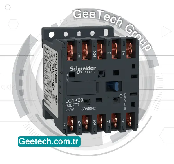
A Schneider contactor is an electrical component that is used to control the flow of electricity in a circuit by opening and closing the contacts to allow or interrupt the current flow.
Schneider Electric is a reputable manufacturer of contactors known for their reliability and efficiency in various industrial applications. These contactors come in different sizes and configurations to meet specific electrical requirements, providing a safe and effective way to manage electricity in machinery and equipment.

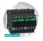
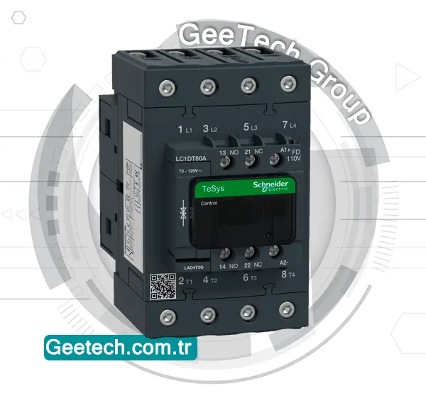
Schneider Electric TeSys D range of contactors, including the LC2DT25P7 model, are commonly used in motor control applications to switch electrical loads on and off.
These contactors are designed for easy installation, high durability, and efficient operation. The LC2DT25P7 contactor is rated for a specific current and voltage range, so it’s important to ensure that it is being used within its designated specifications for safe and reliable performance.
telemecanique contactor
Telemecanique is a brand that was part of Schneider Electric and is well-known for its industrial control and automation products, including contactors. Just like Schneider contactor, Telemecanique contactor are electrical devices used for switching electrical circuits on and off.

Telemecanique contactor are designed to be reliable, durable, and efficient in controlling various electrical loads, such as motors, lighting systems, heating elements, and more. They come in a range of sizes and configurations to cater to different industrial applications and requirements.
These contactors ensure smooth and safe operation of equipment by allowing for the easy management of electrical power distribution in industrial settings. Telemecanique contactors are known for their quality and adherence to industry standards.
LC2DT25P7
The Schneider Electric LC2DT25P7 contactor is a part of the TeSys D series, which are known for their reliability in motor control applications. This particular model has a rated operational current of 25 Amps and is designed to control electrical circuits, particularly for switching motors on and off in various industrial applications.

Reviews
There are no reviews yet.