


schneider electric
Schneider Electric is a multinational corporation specializing in energy management and automation solutions. With operations in over 100 countries, the company offers a wide range of products and services for various industries, including residential, commercial, and industrial.
Schneider Electric is focused on sustainability and innovation, aiming to help their customers manage energy efficiently and reduce their environmental impact.
schneider contactor
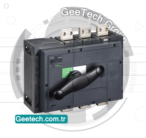
A Schneider contactor is an electrical component that is used to control the flow of electricity in a circuit by opening and closing the contacts to allow or interrupt the current flow.
Schneider Electric is a reputable manufacturer of contactors known for their reliability and efficiency in various industrial applications. These contactors come in different sizes and configurations to meet specific electrical requirements, providing a safe and effective way to manage electricity in machinery and equipment.

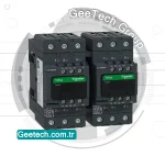
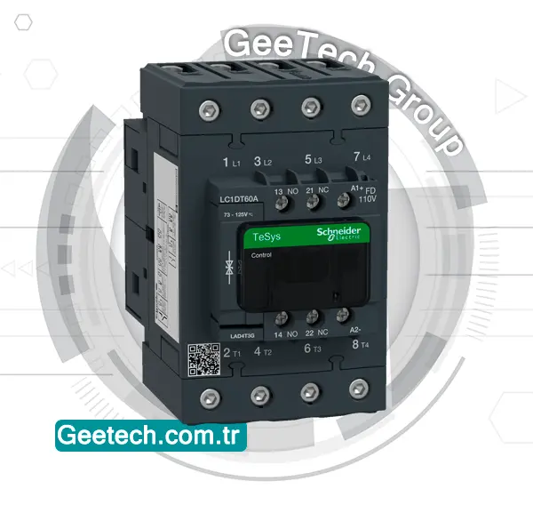
The Schneider Electric contactor LC2D65AF7 is a 65A AC-3/75A AC-1 contactor suitable for controlling electric motors in a variety of industrial applications.
It features a power rating of 30kW at 400/415V and is commonly used in HVAC systems, control panels, and other machinery where reliable switching of electrical circuits is required.
With its compact design and durable construction, the LC2D65AF7 is a reliable and efficient solution for motor control needs.
telemecanique contactor
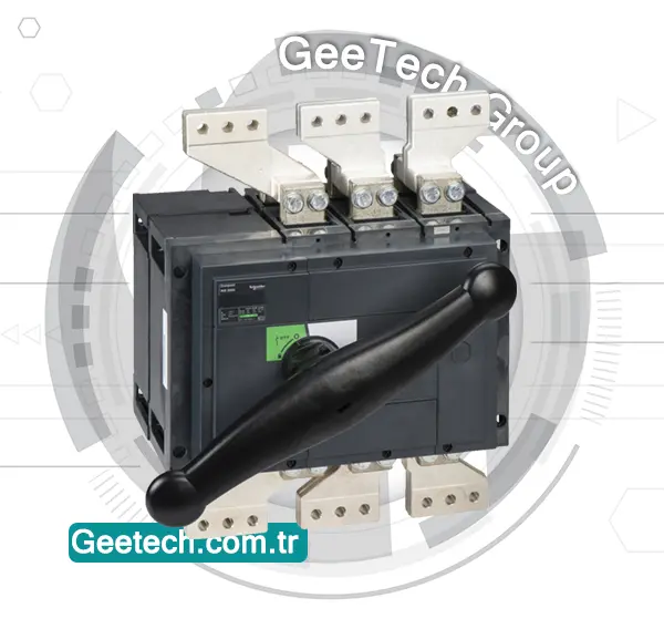
Telemecanique is a brand that was part of Schneider Electric and is well-known for its industrial control and automation products, including contactors. Just like Schneider contactor, Telemecanique contactor are electrical devices used for switching electrical circuits on and off.

Telemecanique contactor are designed to be reliable, durable, and efficient in controlling various electrical loads, such as motors, lighting systems, heating elements, and more. They come in a range of sizes and configurations to cater to different industrial applications and requirements.
These contactors ensure smooth and safe operation of equipment by allowing for the easy management of electrical power distribution in industrial settings. Telemecanique contactors are known for their quality and adherence to industry standards.
lc2d65af7
LC2D65AF7 is a model of a Schneider Electric contactor. It’s part of the TeSys D series of contactors. The LC2D65AF7 contactor is rated for a maximum current of 65 amps. It’s commonly used for controlling electric motors or other power loads in various industrial and commercial applications.

Reviews
There are no reviews yet.