


schneider electric
Schneider Electric is a multinational corporation specializing in energy management and automation solutions. With operations in over 100 countries, the company offers a wide range of products and services for various industries, including residential, commercial, and industrial.
Schneider Electric is focused on sustainability and innovation, aiming to help their customers manage energy efficiently and reduce their environmental impact.
schneider contactor
A Schneider contactor is an electrical component that is used to control the flow of electricity in a circuit by opening and closing the contacts to allow or interrupt the current flow.
Schneider Electric is a reputable manufacturer of contactors known for their reliability and efficiency in various industrial applications. These contactors come in different sizes and configurations to meet specific electrical requirements, providing a safe and effective way to manage electricity in machinery and equipment.

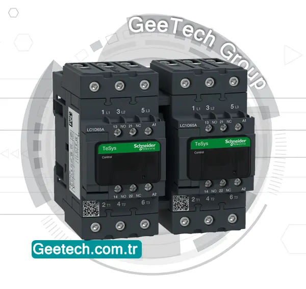
The Schneider Electric LC1DT60AED is a TeSys D series contactor designed for non-inductive load applications up to 60A/690V AC-1. The LC1DT60AED contactor is designed for applications requiring high reliability and durability, with multiple certifications for compliance with international standards.
telemecanique contactor
Telemecanique is a brand that was part of Schneider Electric and is well-known for its industrial control and automation products, including contactors. Just like Schneider contactor, Telemecanique contactor are electrical devices used for switching electrical circuits on and off.

Telemecanique contactor are designed to be reliable, durable, and efficient in controlling various electrical loads, such as motors, lighting systems, heating elements, and more. They come in a range of sizes and configurations to cater to different industrial applications and requirements.
These contactors ensure smooth and safe operation of equipment by allowing for the easy management of electrical power distribution in industrial settings. Telemecanique contactors are known for their quality and adherence to industry standards.
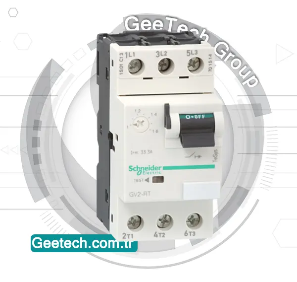
LC1DT60AED
Contactor LC1DT60AED is a TeSys D series contactor suitable for non-inductive load applications up to 60A/690V AC-1, featuring a 48V DC coil with transient suppressor module, 1NO+1NC built-in auxiliary contacts, EverLink BTR screw connectors for power connection, screw clamp terminals for control connection, and a compact design for DIN-rail mounting or screw fixing, providing high reliability and durability for operating rates up to 3600 cycles/hour in environments up to 60°C.

Reviews
There are no reviews yet.