


LC1D65AU7
TeSys; TeSys Deca, Contactor, 3P(3 NO), AC-3/AC-3e, 0 to 440V, 65A, 240VAC 50/60Hz coil
- Stock status:
- Call for availability
- Manufacturer:
- Schneider
- Product code:
- LC1D65AU7
Main documents
Related products
| Range | TeSys TeSys Deca |
|---|---|
| Range of product | TeSys Deca |
| Product or component type | Contactor |
| Device short name | LC1D |
| contactor application | Motor control Resistive load |
| utilisation category | AC-4 AC-1 AC-3 AC-3e |
| Poles description | 3P |
| [Ue] rated operational voltage | Power circuit: <= 690 V AC 25…400 Hz Power circuit: <= 300 V DC |
| [Ie] rated operational current | 80 A (at <60 °C) at <= 440 V AC AC-1 for power circuit 65 A (at <60 °C) at <= 440 V AC AC-3 for power circuit 65 A (at <60 °C) at <= 440 V AC AC-3e for power circuit |
| [Uc] control circuit voltage | 240 V AC 50/60 Hz |
| Motor power kW | 11 kW at 400 V AC 50/60 Hz (AC-4) 18.5 kW at 220…230 V AC 50/60 Hz (AC-3) 30 kW at 380…400 V AC 50/60 Hz (AC-3) 37 kW at 500 V AC 50/60 Hz (AC-3) 37 kW at 660…690 V AC 50/60 Hz (AC-3) 18.5 kW at 220…230 V AC 50/60 Hz (AC-3e) 30 kW at 380…400 V AC 50/60 Hz (AC-3e) 37 kW at 500 V AC 50/60 Hz (AC-3e) 37 kW at 660…690 V AC 50/60 Hz (AC-3e) |
|---|---|
| Motor power hp | 40 hp at 460/480 V AC 50/60 Hz for 3 phases motors 5 hp at 115 V AC 50/60 Hz for 1 phase motors 10 hp at 230/240 V AC 50/60 Hz for 1 phase motors 20 hp at 200/208 V AC 50/60 Hz for 3 phases motors 20 hp at 230/240 V AC 50/60 Hz for 3 phases motors 50 hp at 575/600 V AC 50/60 Hz for 3 phases motors |
| Compatibility code | LC1D |
| Pole contact composition | 3 NO |
| Protective cover | With |
| [Ith] conventional free air thermal current | 10 A (at 60 °C) for signalling circuit 80 A (at 60 °C) for power circuit |
| Irms rated making capacity | 140 A AC for signalling circuit conforming to IEC 60947-5-1 250 A DC for signalling circuit conforming to IEC 60947-5-1 1000 A at 440 V for power circuit conforming to IEC 60947 |
| Rated breaking capacity | 1000 A at 440 V for power circuit conforming to IEC 60947 |
| [Icw] rated short-time withstand current | 640 A 40 °C – 10 s for power circuit 900 A 40 °C – 1 s for power circuit 110 A 40 °C – 10 min for power circuit 260 A 40 °C – 1 min for power circuit 100 A – 1 s for signalling circuit 120 A – 500 ms for signalling circuit 140 A – 100 ms for signalling circuit |
| Associated fuse rating | 10 A gG for signalling circuit conforming to IEC 60947-5-1 125 A gG at <= 690 V coordination type 1 for power circuit 125 A gG at <= 690 V coordination type 2 for power circuit |
| Average impedance | 1.5 mOhm – Ith 80 A 50 Hz for power circuit |
| Power dissipation per pole | 9.6 W AC-1 6.3 W AC-3 6.3 W AC-3e |
| [Ui] rated insulation voltage | Power circuit: 600 V CSA certified Power circuit: 600 V UL certified Signalling circuit: 690 V conforming to IEC 60947-1 Signalling circuit: 600 V CSA certified Signalling circuit: 600 V UL certified Power circuit: 690 V conforming to IEC 60947-4-1 |
| Overvoltage category | III |
| Pollution degree | 3 |
| [Uimp] rated impulse withstand voltage | 6 kV conforming to IEC 60947 |
| Safety reliability level | B10d = 1369863 cycles contactor with nominal load conforming to EN/ISO 13849-1 B10d = 20000000 cycles contactor with mechanical load conforming to EN/ISO 13849-1 |
| Mechanical durability | 6 Mcycles |
| Electrical durability | 1.4 Mcycles 80 A AC-1 at Ue <= 440 V 1.45 Mcycles 65 A AC-3 at Ue <= 440 V 1.45 Mcycles 65 A AC-3e at Ue <= 440 V |
| Control circuit type | AC at 50/60 Hz |
| Coil technology | Without built-in suppressor module |
| Control circuit voltage limits | 0.3…0.6 Uc (-40…70 °C):drop-out AC 50/60 Hz 0.8…1.1 Uc (-40…60 °C):operational AC 50 Hz 0.85…1.1 Uc (-40…60 °C):operational AC 60 Hz 1…1.1 Uc (60…70 °C):operational AC 50/60 Hz |
| Inrush power in VA | 140 VA 60 Hz cos phi 0.75 (at 20 °C) 160 VA 50 Hz cos phi 0.75 (at 20 °C) |
| Hold-in power consumption in VA | 13 VA 60 Hz cos phi 0.3 (at 20 °C) 15 VA 50 Hz cos phi 0.3 (at 20 °C) |
| Heat dissipation | 4…5 W at 50/60 Hz |
| Operating time | 4…19 ms opening 12…26 ms closing |
| Maximum operating rate | 3600 cyc/h 60 °C |
| Connections – terminals | Control circuit: screw clamp terminals 2 1…2.5 mm² – cable stiffness: flexible with cable end Control circuit: screw clamp terminals 1 1…4 mm² – cable stiffness: flexible without cable end Control circuit: screw clamp terminals 2 1…4 mm² – cable stiffness: flexible without cable end Control circuit: screw clamp terminals 1 1…4 mm² – cable stiffness: flexible with cable end Control circuit: screw clamp terminals 1 1…4 mm² – cable stiffness: solid without cable end Control circuit: screw clamp terminals 2 1…4 mm² – cable stiffness: solid without cable end Power circuit: screw connection 1 1…35 mm² – cable stiffness: flexible without cable end Power circuit: screw connection 2 1…25 mm² – cable stiffness: flexible without cable end Power circuit: screw connection 1 1…35 mm² – cable stiffness: flexible with cable end Power circuit: screw connection 2 1…25 mm² – cable stiffness: flexible with cable end Power circuit: screw connection 1 1…35 mm² – cable stiffness: solid without cable end Power circuit: screw connection 2 1…25 mm² – cable stiffness: solid without cable end |
| Tightening torque | Control circuit: 1.7 N.m – on EverLink BTR screw connectors – with screwdriver flat Ø 6 mm Control circuit: 1.7 N.m – on EverLink BTR screw connectors – with screwdriver Philips No 2 Power circuit: 8 N.m – on EverLink BTR screw connectors – cable 25…35 mm² hexagonal screw head 4 mm Power circuit: 5 N.m – on EverLink BTR screw connectors – cable 1…25 mm² hexagonal screw head 4 mm Control circuit: 1.7 N.m – on EverLink BTR screw connectors – with screwdriver pozidriv No 2 Power circuit: 2.5 N.m – on EverLink BTR screw connectors – with screwdriver pozidriv No 2 |
| Auxiliary contact composition | 1 NO + 1 NC |
| Auxiliary contacts type | Type mechanically linked 1 NO + 1 NC conforming to IEC 60947-5-1 type mirror contact 1 NC conforming to IEC 60947-4-1 |
| Signalling circuit frequency | 25…400 Hz |
| Minimum switching voltage | 17 V for signalling circuit |
| Minimum switching current | 5 mA for signalling circuit |
| Insulation resistance | > 10 MOhm for signalling circuit |
| Non-overlap time | 1.5 ms on de-energisation between NC and NO contact 1.5 ms on energisation between NC and NO contact |
| mounting support | Rail Plate |
| Standards | CSA C22.2 No 14 EN 60947-4-1 EN 60947-5-1 IEC 60947-4-1 IEC 60947-5-1 UL 508 IEC 60335-1 |
|---|---|
| product certifications | GOST UL CSA CCC |
| IP degree of protection | IP20 front face conforming to IEC 60529 |
| Protective treatment | TH conforming to IEC 60068-2-30 |
| Climatic withstand | Conforming to IACS E10 exposure to damp heat conforming to IEC 60947-1 Annex Q category D exposure to damp heat |
| Permissible ambient air temperature around the device | -40…60 °C 60…70 °C with derating |
| Operating altitude | 0…3000 m |
| Fire resistance | 850 °C conforming to IEC 60695-2-1 |
| Flame retardance | V1 conforming to UL 94 |
| Mechanical robustness | Vibrations contactor open (2 Gn, 5…300 Hz) Vibrations contactor closed (4 Gn, 5…300 Hz) Shocks contactor closed (15 Gn for 11 ms) Shocks contactor open (10 Gn for 11 ms) |
| height | 122 mm |
| Width | 55 mm |
| Depth | 120 mm |
| Net weight | 0.86 kg |
| Unit Type of Package 1 | PCE |
|---|---|
| Number of Units in Package 1 | 1 |
| Package 1 Height | 6.2 cm |
| Package 1 Width | 13.7 cm |
| Package 1 Length | 15.2 cm |
| Package 1 Weight | 953.0 g |
| Unit Type of Package 2 | S02 |
| Number of Units in Package 2 | 10 |
| Package 2 Height | 15.0 cm |
| Package 2 Width | 30.0 cm |
| Package 2 Length | 40.0 cm |
| Package 2 Weight | 9.985 kg |
| Unit Type of Package 3 | P06 |
| Number of Units in Package 3 | 160 |
| Package 3 Height | 77.0 cm |
| Package 3 Width | 80.0 cm |
| Package 3 Length | 60.0 cm |
| Package 3 Weight | 168.26 kg |
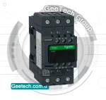
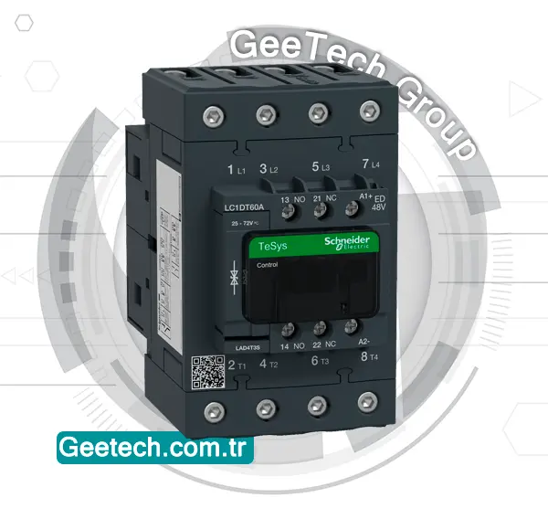
Product Description
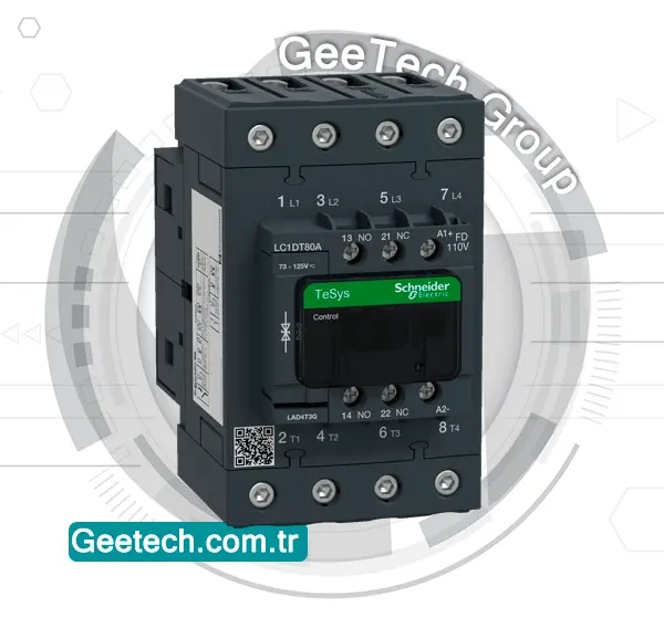
LC1D65AU7
The Schneider Electric LC1D65AU7 is a TeSys Deca 3-pole contactor (3NO main contacts) designed for reliable motor control and load switching in industrial and commercial applications.
It supports AC-3/AC-3e utilization categories for motor loads up to 65 A at 440 V AC (30 kW at 400 V) and AC-1 for resistive loads up to 80 A.
This model comes equipped with a 240 V AC 50/60 Hz coil, 1NO + 1NC built-in auxiliary contacts (with NC mirror contact certification), and features EverLink BTR screw connectors for secure power wiring and screw clamp terminals for control wiring.
With a high mechanical endurance of up to 3,600 operating cycles/hour and operating temperature capability up to 60°C, it delivers long-lasting performance in demanding environments. Its compact 55 mm width design allows for DIN rail mounting or screw fixing, making installation flexible and space-efficient.

Key Specifications:
- Product Range: TeSys Deca (LC1D Series)
- Product Type: Contactor
- Application: Motor control, resistive load switching
- Number of Poles: 3P (3NO main contacts)
- Utilization Categories: AC-1, AC-3, AC-3e, AC-4
- Power circuit: up to 690 V AC (25…400 Hz)
- Power circuit: up to 300 V DC
Applications:
- Industrial motor starters
- HVAC systems
- Pump and compressor control
- Conveyor and automation systems
- General-purpose load switching
Summary:
The LC1D65AU7 TeSys Deca contactor offers high-performance motor control up to 65 A with a 240 V AC coil, delivering compact size, robust connections, and durability in tough operating conditions. Its compatibility with multiple international standards makes it ideal for global installation needs.
Frequently Asked Questions
what is a contactor?
✅A contactor is an electrical relay used to control a high-power circuit with a lower-power signal. It consists of a coil that, when energized, creates a magnetic field to close or open the contacts within the contactor, allowing or interrupting the flow of electricity to the controlled load.
Contactors are commonly used in applications where high currents need to be switched, such as controlling electric motors, lighting systems, heating elements, and other high-power equipment. They are designed to handle frequent switching and high currents efficiently, making them essential components in industrial and commercial electrical systems.
To read more about contactors and other electrical industrial parts, you can refer to the blog section of GeeTech Group at the following address
what is a contactor used for?
✅A contactor serves as a specialized relay designed to control the opening and closing of electrical circuits. Primarily utilized in conjunction with electric motors and lighting systems, they facilitate efficient switching operations.
Why do we need contactors?
✅A contactor is employed to safely and indirectly manage the operation of high-power electrical equipment, such as motors, fans, and pumps, by interfacing with a PLC. By using a contactor, we ensure the secure control of heavy-duty, high-voltage devices without directly connecting them to the PLC.
What is a contactor vs relay
✅Contactors excel in managing high-current loads, whereas relays are ideal for low to medium-current applications. This contrast stems from their distinct designs, with contactors boasting larger, sturdier auxiliary contacts tailored to handle elevated currents efficiently.
what is a magnetic contactor?
✅A magnetic contactor is an electromechanical device used to control the flow of electricity in an electrical circuit. It consists of a coil that, when energized, creates a magnetic field to close or open the contacts within the contactor.
Magnetic contactors are commonly used in industrial and commercial applications to switch high-power loads, such as electric motors, lighting systems, heating elements, and other electrical equipment. They are known for their reliability, durability, and ability to handle high currents, making them essential components in various electrical control systems.
what is auxiliary contactor?
✅Auxiliary contactors are additional sets of contacts added to a primary contactor to perform auxiliary functions within an electrical control system. These contacts are typically used to provide feedback or signaling, monitor the status of the main contacts, or control auxiliary devices such as indicator lights, timers, or interlocks.
Auxiliary contactors are commonly found in industrial control panels, motor control centers, and other electrical equipment where precise control and monitoring of circuits are necessary. They play a crucial role in enhancing the functionality and safety of electrical systems by providing additional control and feedback options.

Reviews
There are no reviews yet.